Introduction
We simulate a simple dipole in CST Studio Suite® in order to find out the effect of its gap position and size on its frequency, impedance and VSWR. The dipole has a length of 50 cm, wire radius of 2 mm and made of perfectly conducting material.
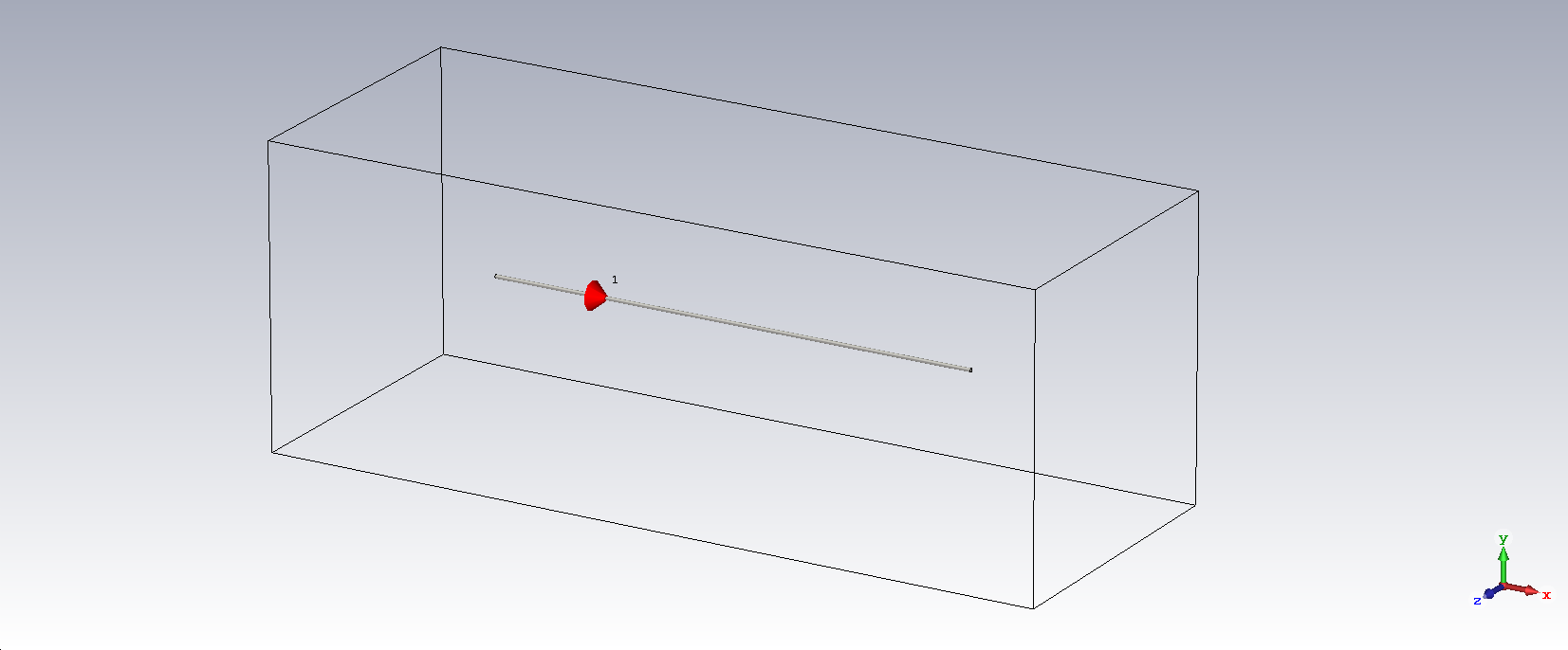
Position sweep
Keeping the feed gap size constant to 1 cm, but we sweep its position from center (offset = 0) to one side (offset = 240).

Mainly two resonances appear at 277 MHz and a higher harmonic at 850 MHz. If the position is moved halfway through the dipole, then a third resonance appears around 565 MHz.
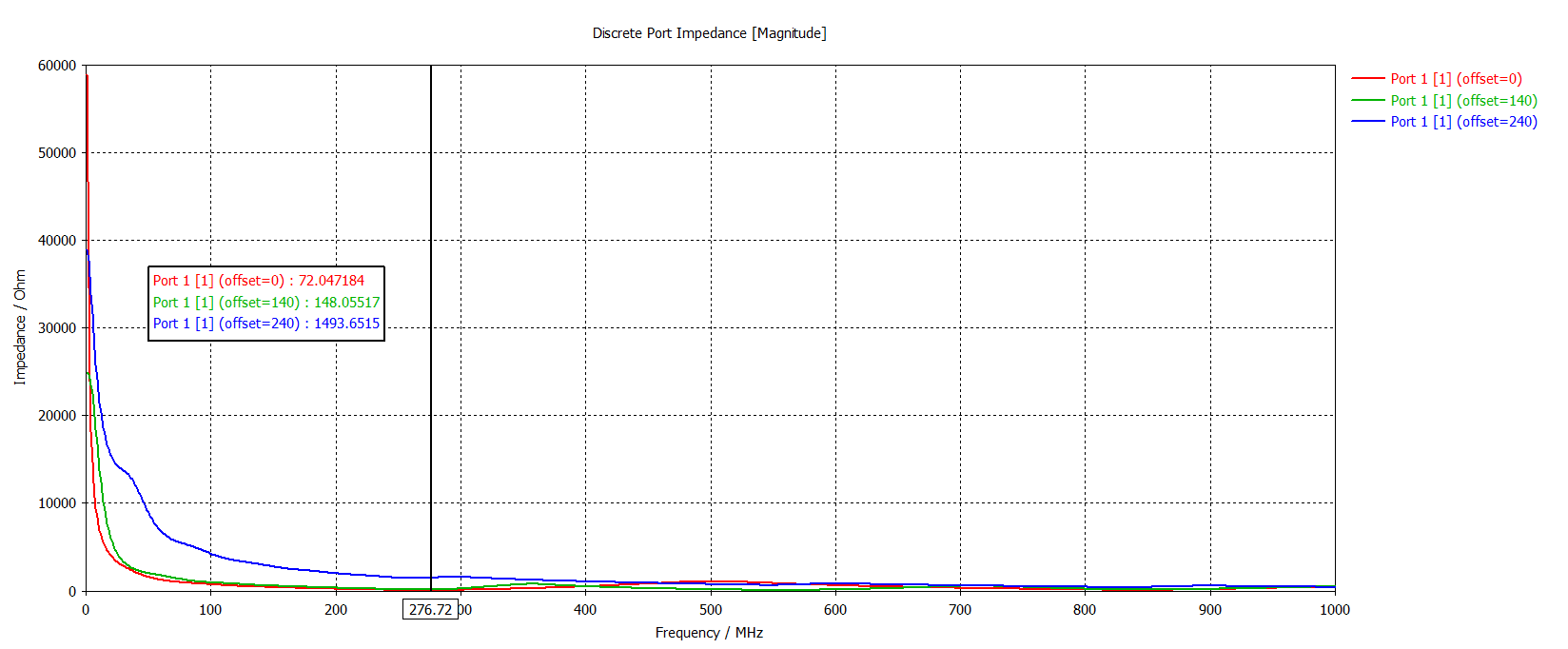
It is clear that the lowest impedance at the first resonance is as expected at the center.
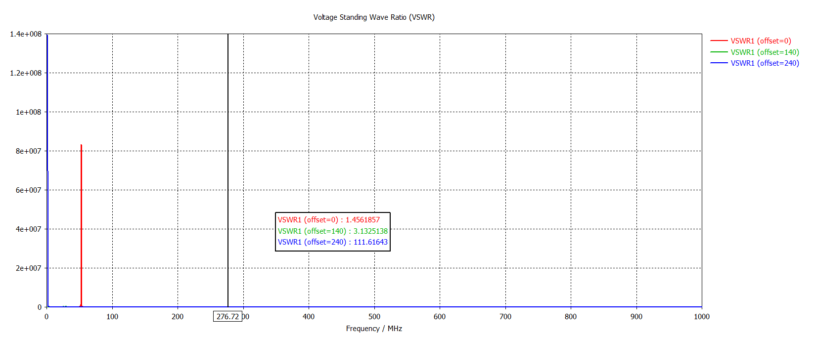
Finally the lowest VSWR is also whenever the feed is at the center.
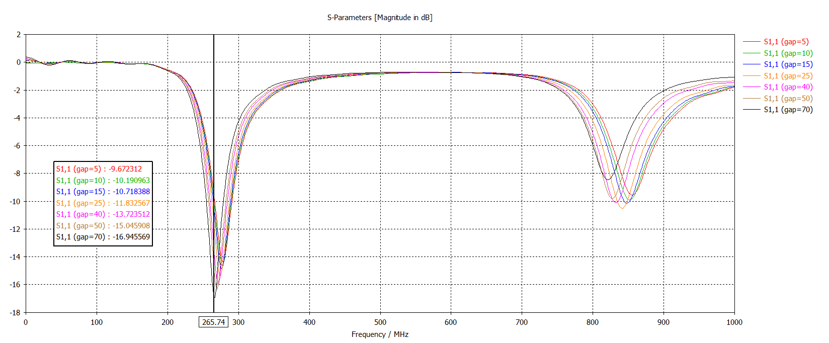
Feed Gap size sweep
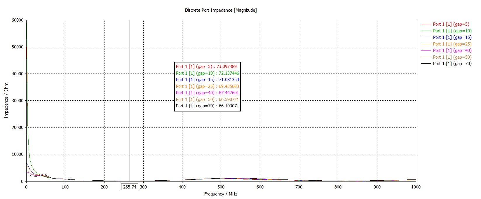
Now we keep the gap position fixed at the center, and then sweep the gap size:
Frequency:
Impedance:
VSWR:
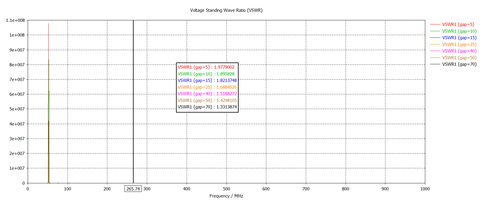
One can see that the effect on resonance frequencies, VSWR and impedance is not dramatic.
Radiation pattern
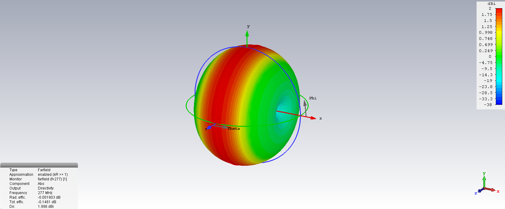
Finally the farfield radiation pattern in 3D:
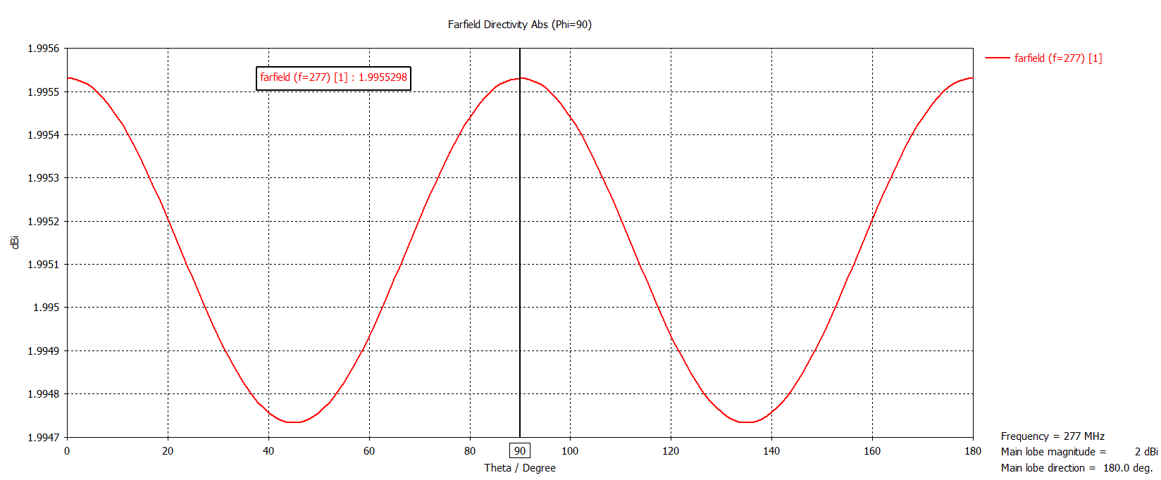
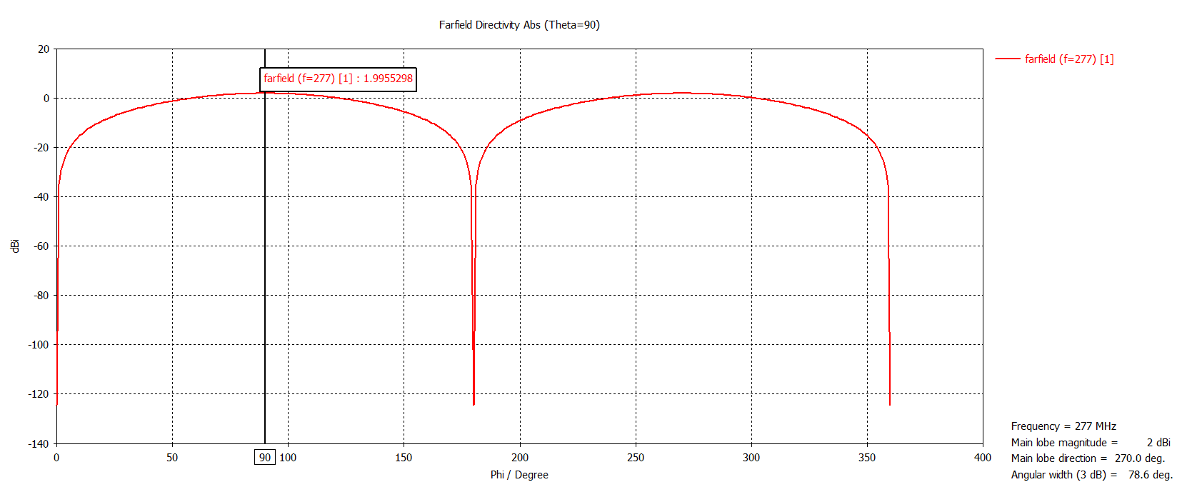
Cut along constant Phi:
Cut along constant Theta:
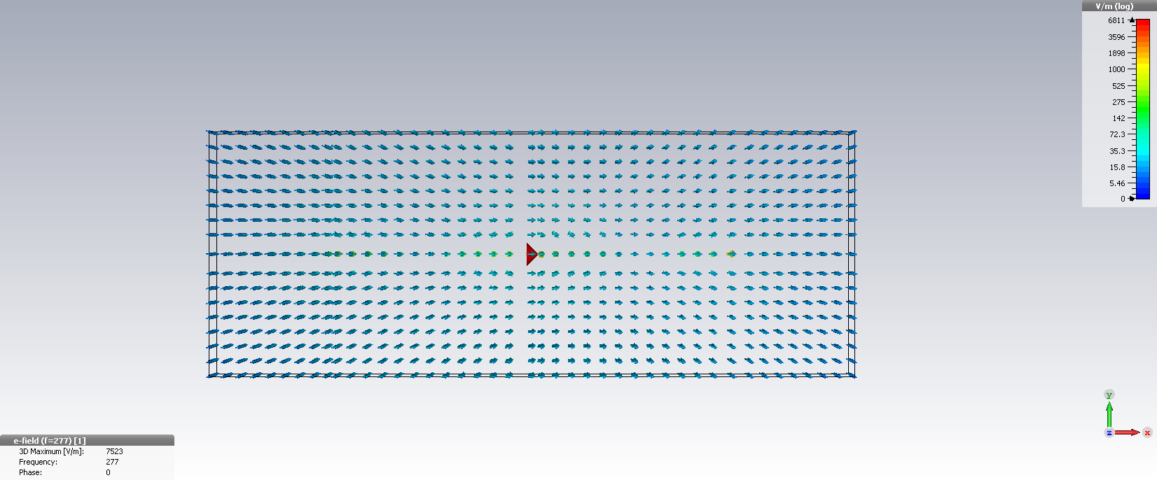
Instantaneous electric field (phase 0):
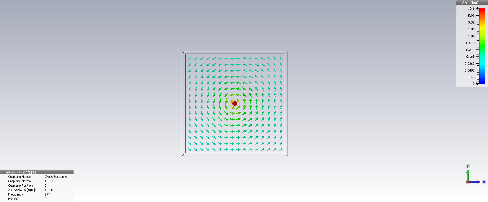
Instantaneous magnetic field (phase 0), looking from the side:
Surface current:
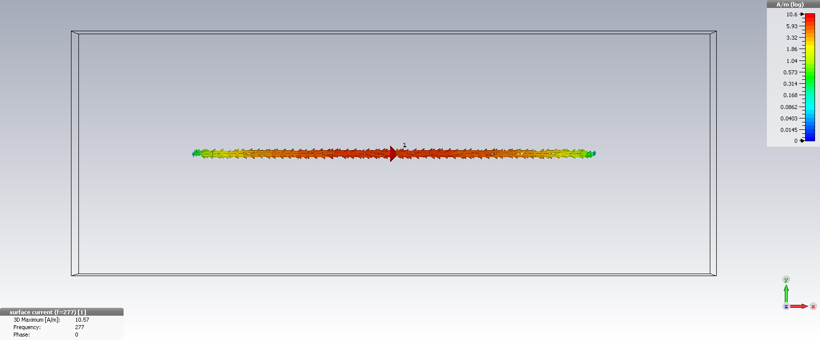 Clearly visible the highest amount of current around center.
Power flow:
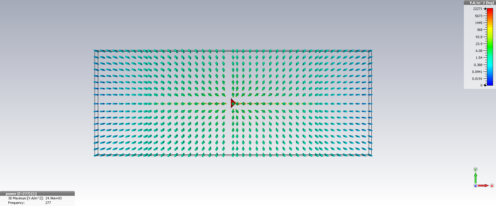
Note the nicely outwards oriented arrows. I really like the power flow diagram very much.
References
- [Sil01] H. W. Silver et. al., The ARRL Antenna Book For Radio Communications, Radio Society of Great Britain, 2001.