Exchange of preamps at MW11 and MW31, 19 - 20.04.2022. The new generation preamps which we put with Ivan and Elena are low gain, these are bad for our purpose. Thus had to be replaced again.
MW11: preamp V5 replaced. The gain is adjusted to ~160 for anode signals and ~400 (inverting) for the cathodes, see plots for anode and cathodes from M. Traeger. Very probably that L, R, U, D are mixed up!
MW31: R and L preamps replaced. The gain is adjusted to ~160 for anode signals and ~400 (inverting) for the cathodes, see plots for anode and cathodes from M. Traeger. Preamp box to be picked-up from det lab and installed on detector!
Gas test with Obrisphere 3600 for O2 content, 05.04.2022 and 19 - 20.04.2022:
MW11: Orbisphere reading O2 content < 120 ppm, this is a good number, no leak.
MW31: at 5 l/h rate outside (mixing cabinet) there is 3 l/h gas rate inside on the detector output after gas valve S3_2 was completely opened (was partly closed?). Orbisphere reading O2 content < 200 ppm, no leak.
MW51: at 5 l/h rate outside NO rate on the detector input. 10 l/h outside - 3 l/h rate on input, but 0 l/h i.e. NOTHING on detector output. There is for sure a big leak!
MW71: Orbisphere reading O2 content < 450 ppm, a small leak!
MW81: Orbisphere reading O2 content < 250 ppm, no leak.
MW81+MW82: Orbisphere reading O2 content < 110 ppm, no leak.
MWPC11, 31, 82 are operational. 31: preamps for R,L cathodes were exchanged, their polarity is now positive. It is not an issue, TDC works with both polarities.
MWPC51, 71, 81 showed no rate with sources (either 90Sr or 60Co). Some signals appear < 1 per minute, maybe MIPs. Efficiency is still very low.
Gas ratio was again reported wrong and fixed in mid December 2021 by Holger Risch from det lab. Before ratio was 40/60 (Ar/CO2), but unknown for how long (since March 2021 or later?) and how it happened to change. From 10.12.2021 it is correctly calibrated again to Ar/CO2 80/20. Be careful: meter of CO2 gas flow is broken - shows always zero!
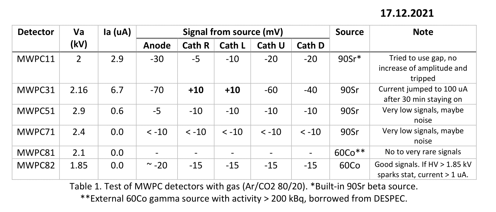
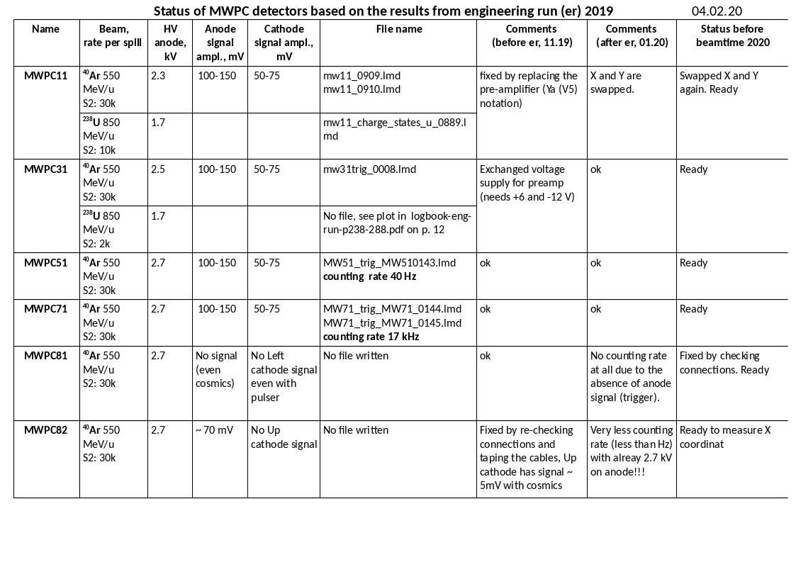
See Table from 17.12.2021 for latest test results.
Performance during previous beamtimes
FRS beamtime 2021
During the R3B exp. S455 (28.03 - 01.04) with 238U was found out:
MWPC31 is missing both Left and Right signals cathodes (also no pulser passes through).
MWPC51, 71, 81 show only up to -60 mV signals (with U should be more or?) with voltages around 2 - 2.3 kV. Futher increase of voltage was risky. Also, detectors counted much less than scintillators, efficiency about 20% only? why?
MWPC81 exhibits constant noise (some harmonic function) of about 50 mV.
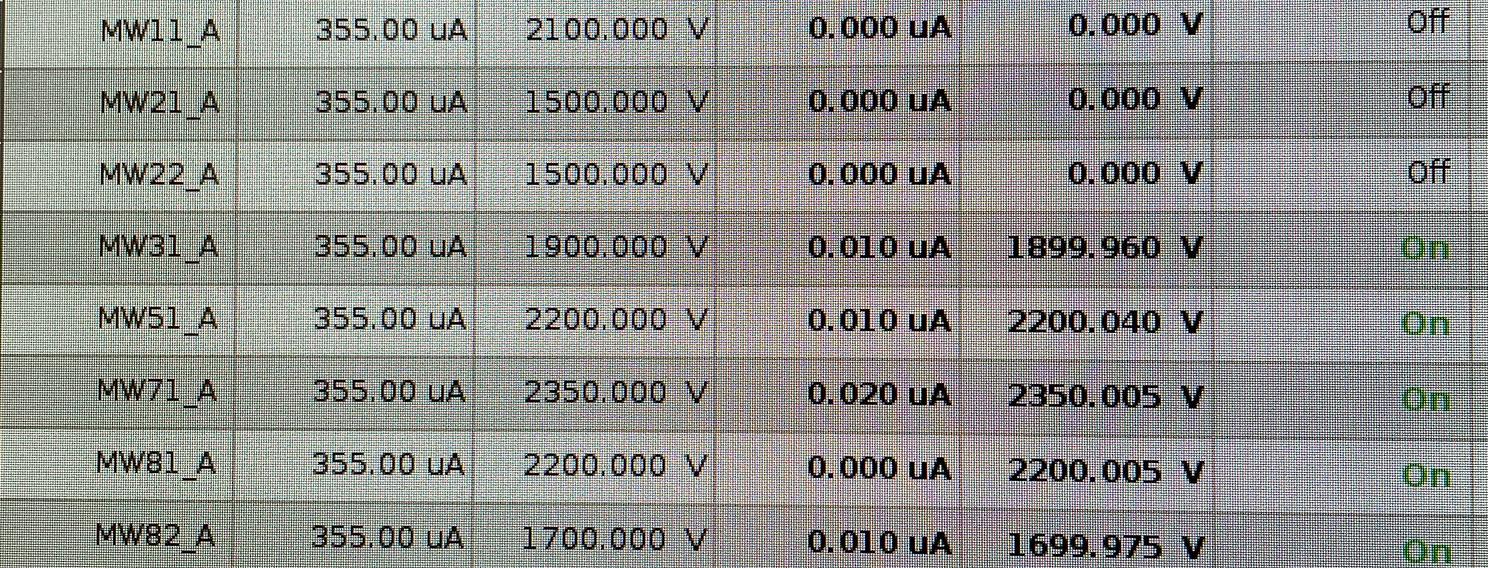
According to FRS logbook (page 51), MWPC82 signal of about 10 mV is hardly visible within the noise of 10 mV. I think voltage was never increased from 1.7 kV, see screenshot from Geco below!
According to same logbook, the drive of MWPC81 was "green" in the device control, however physically still stayed in the the beam line! Thus, it had to be moved out manually from the electronics room of Messhuette.
Gas mixture prolem was revealed (end March):
The gas misture requred for correct MWPCs operation is a mix of Argon (80%) and CO2 (20%). The level of CO2 was discovered to be 0%, this was fixed with the help of det lab colleagues. This issue could be a source of such low efficiency of the detectors.
Later, during the next R3B run S515 (24.04 - 02. 05) with 136Xe the status was the following:
MWPC81. It was operated at 2.3 kV anode voltage, still constant noise (some harmonic function) of about 50 mV is there. And still VERY LOW EFFICIENCY of about 1%
MWPC82. During evening 24.04 it was operated at 2.5 kV anode voltage, efficiency was about 20% higher than MWPC81. However, on next day 25.04 MWPC82 stopped working, i.e. no signals at all with HV applied. Was is burned? Probably.
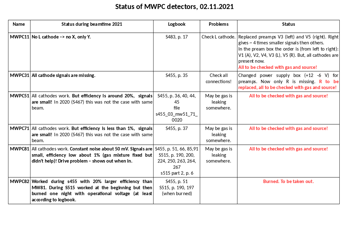
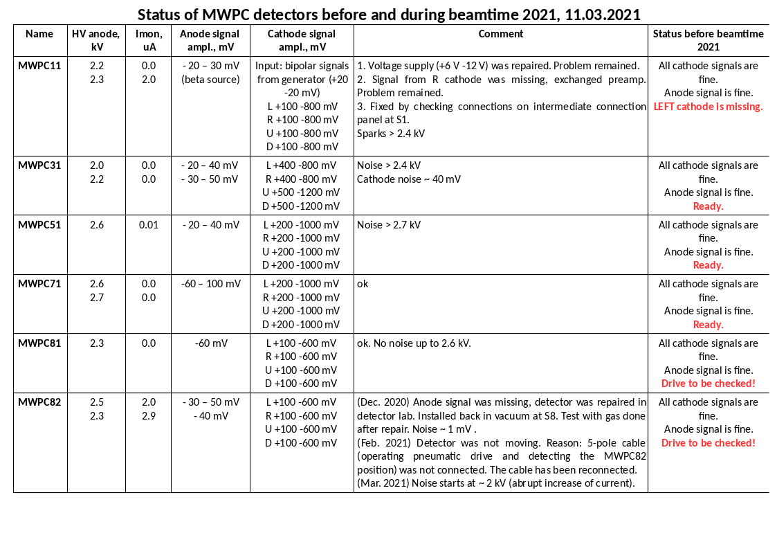
Before FRS beamtime 2021
After engineering run 2019 (before FRS beamtime 2020)
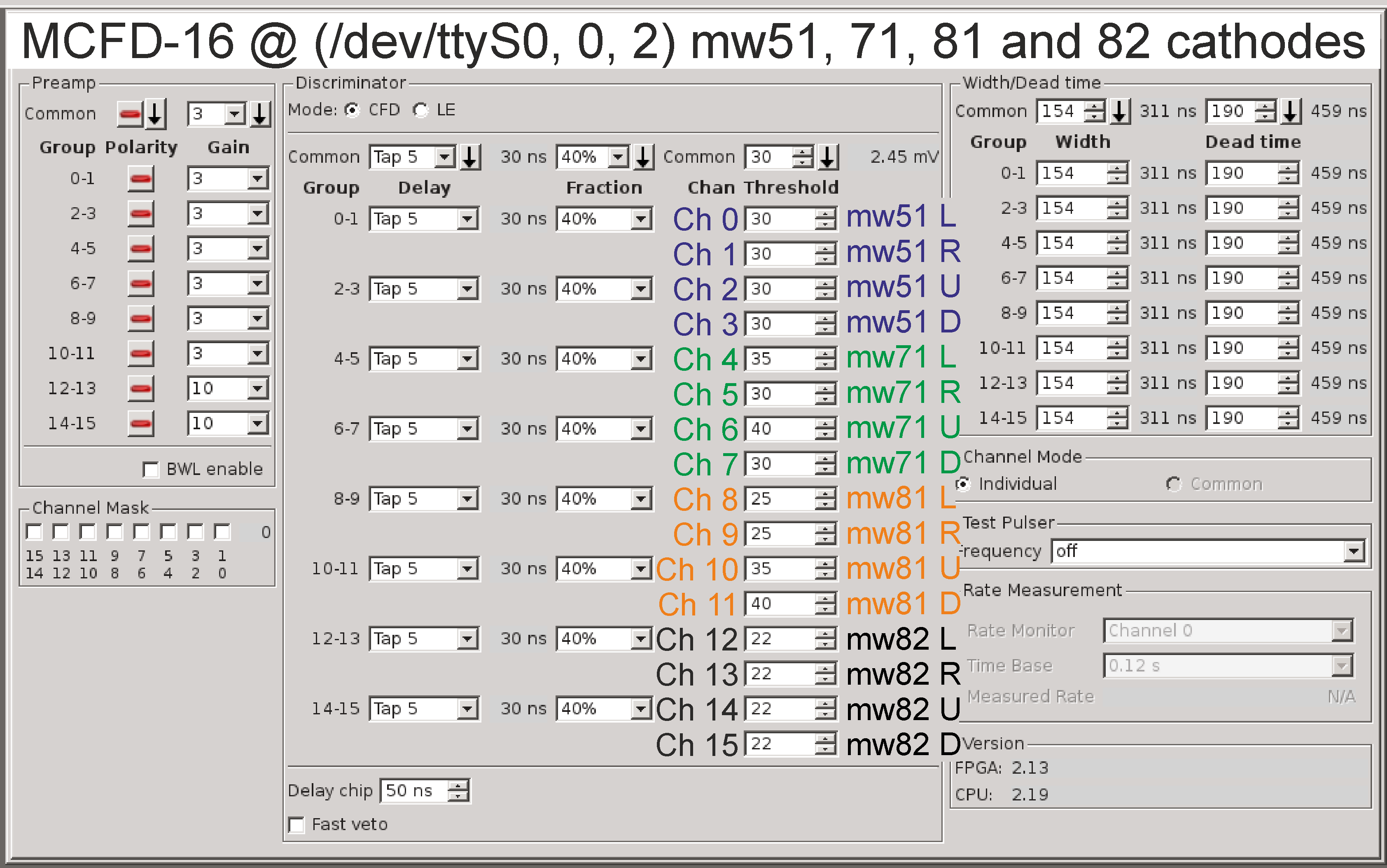
How to operate CFDs of MWPC
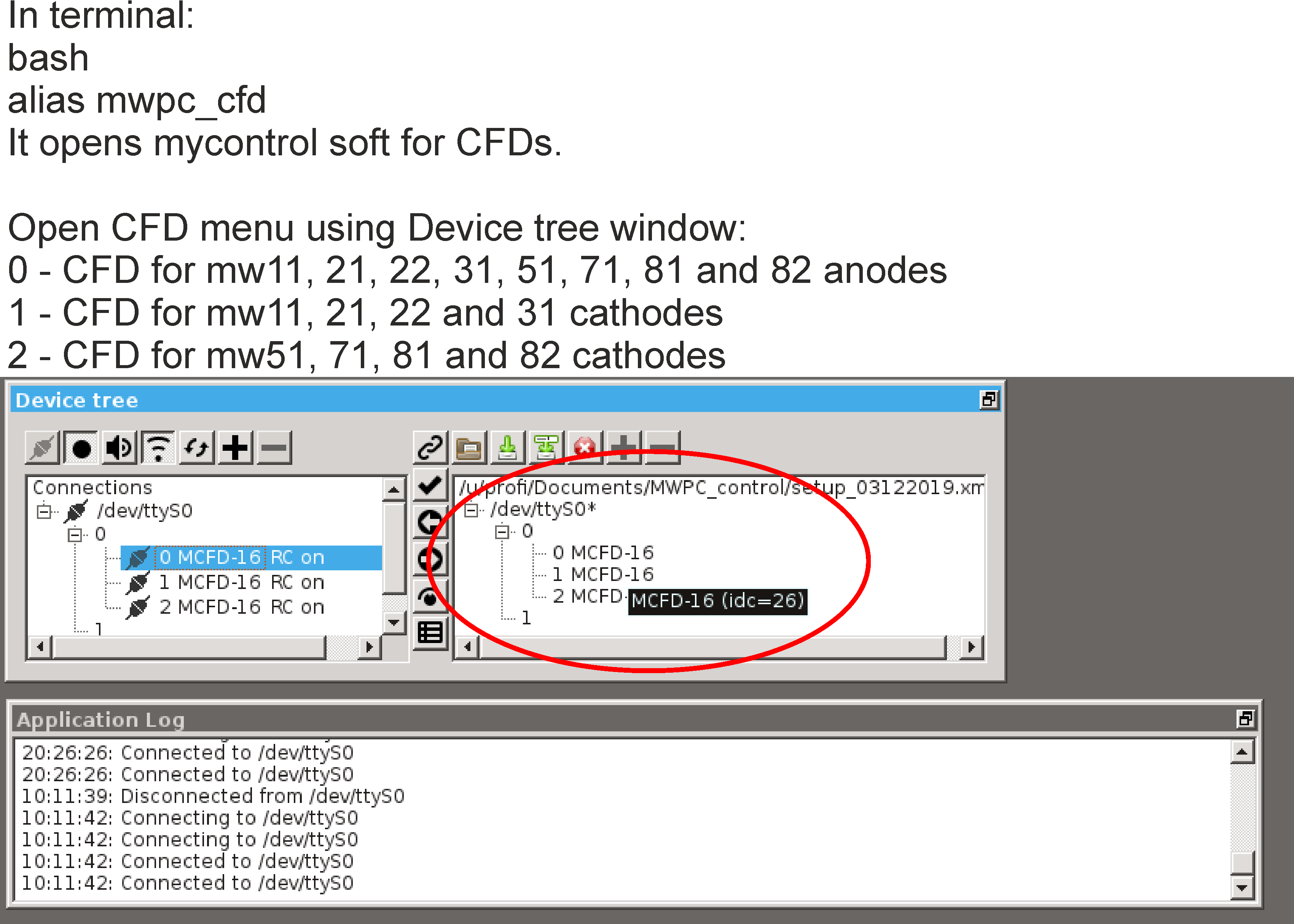
Important note: CFDs are controlled using Mesycontrol software. This software is installed under profi user and is also used to control other Mesytech modules e.g. MCFDs for ToF scintillators. Inside the software, one can open the setup file and choose which CFDs to control. However, the CFDs of MWPCs can be controlled only locally, meaning on the machine to which the remote control module (MRC) is physically connected to! This machine is lxg1267, it is located in the Messhuette ("go4" machine). Connection via ssh does not work, so please go locally.
1. Open mesytec control software for CFDs under profi user locally on lxg1267 machine
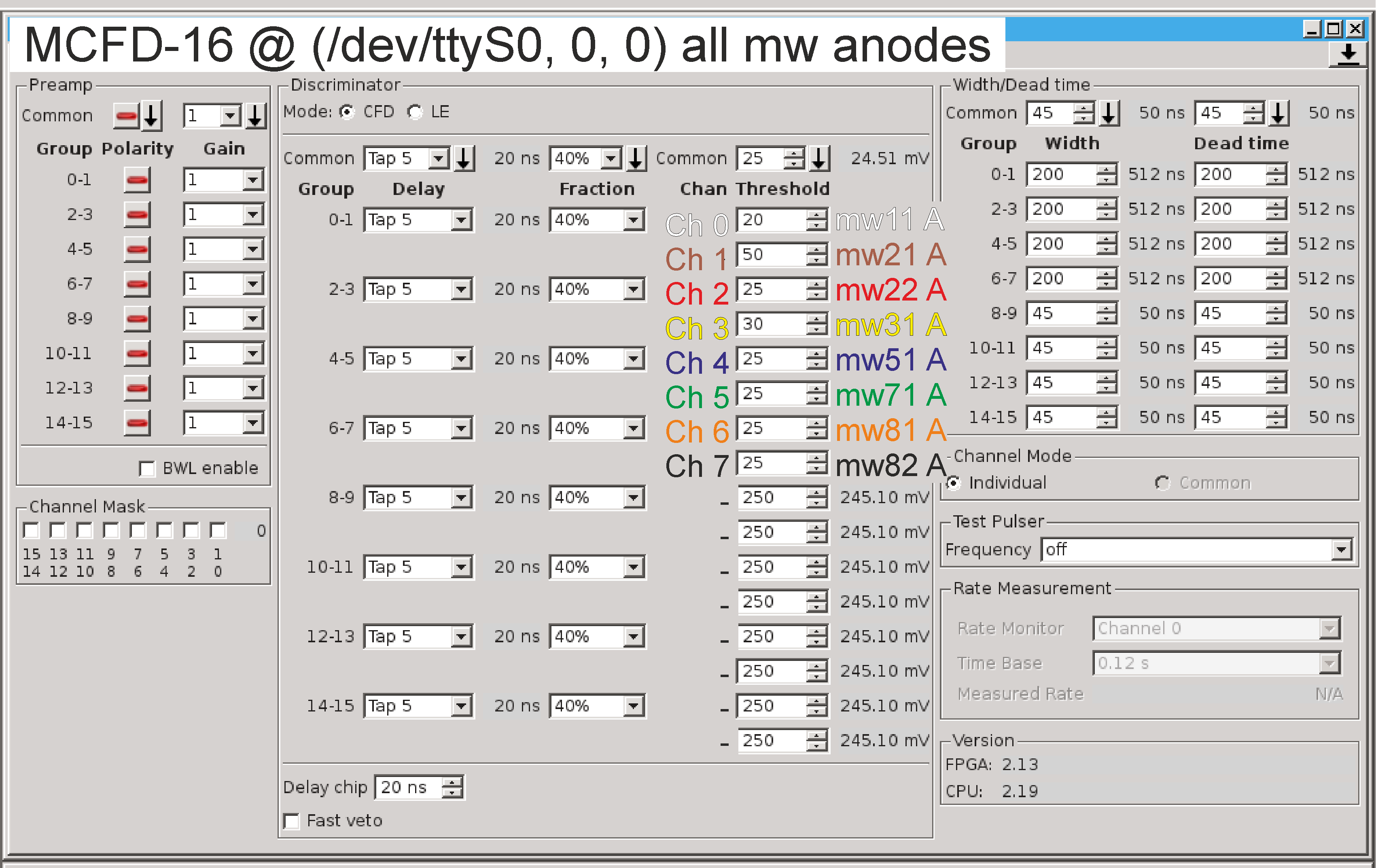
2. Select thresholds for anodes. The typed value is automatically sent.
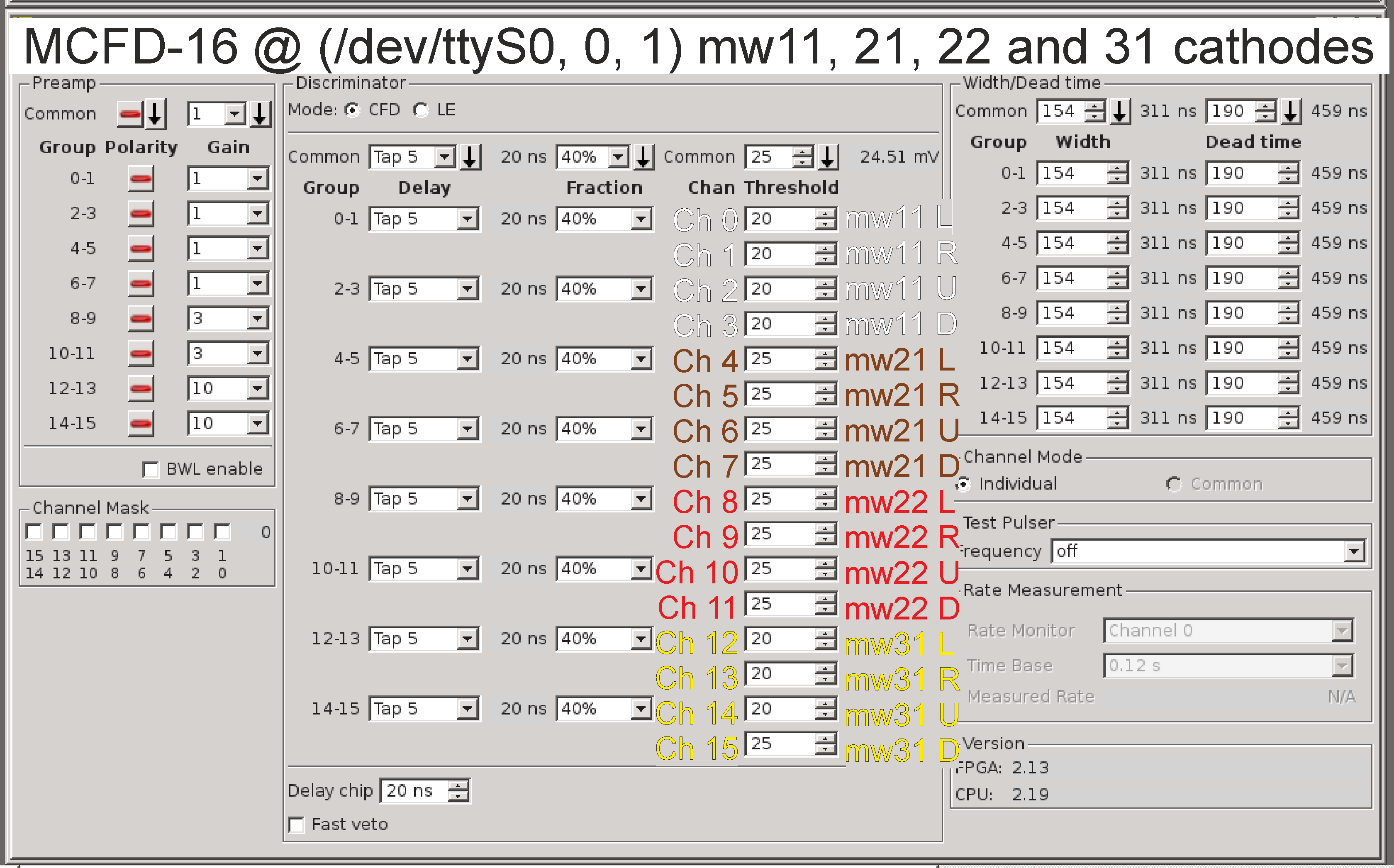
3. Select thresholds for cathodes. The typed value is automatically sent.
4. The setup file can be saved to or loaded from /u/profi/Documents/MWPC_control
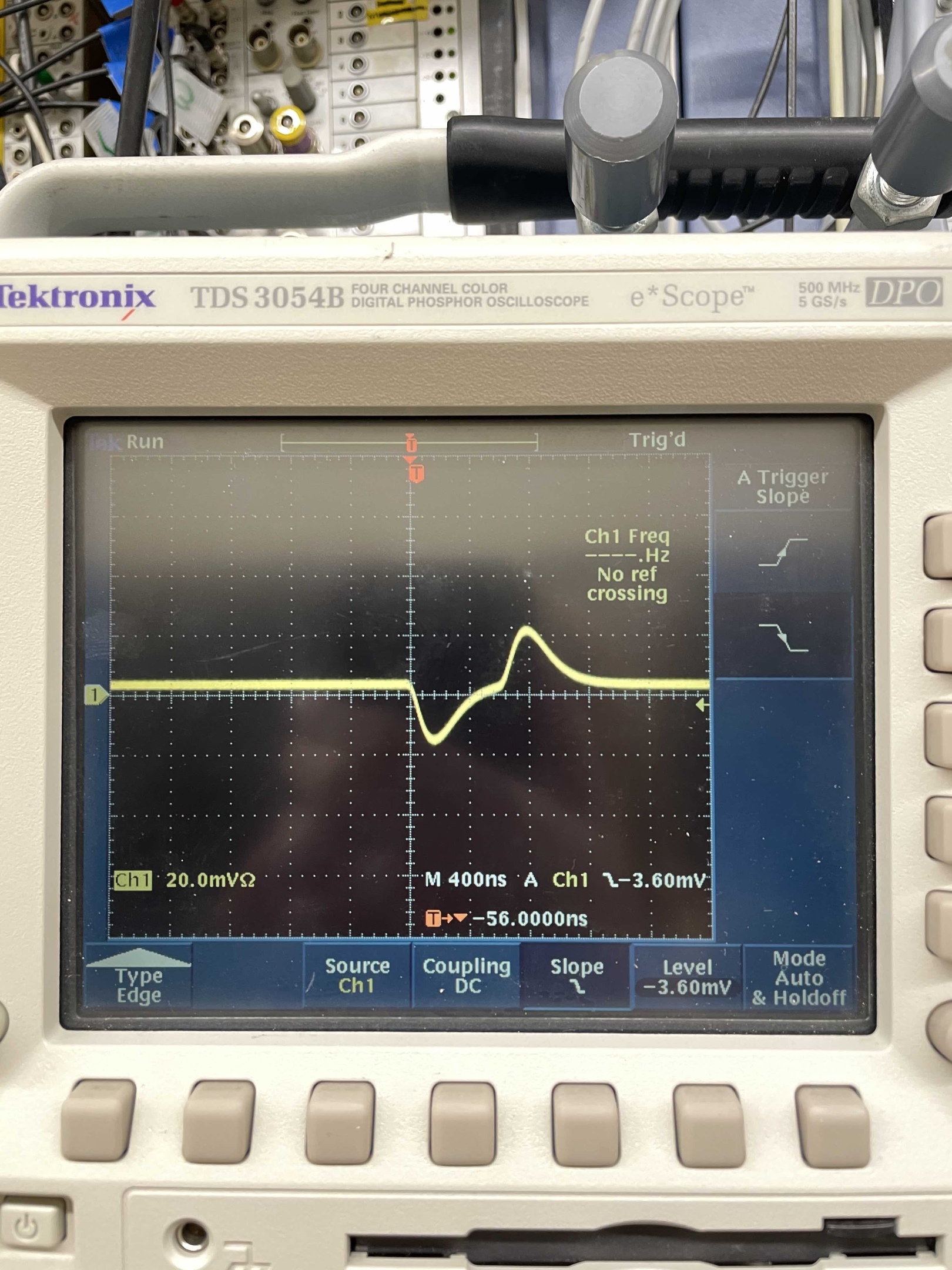
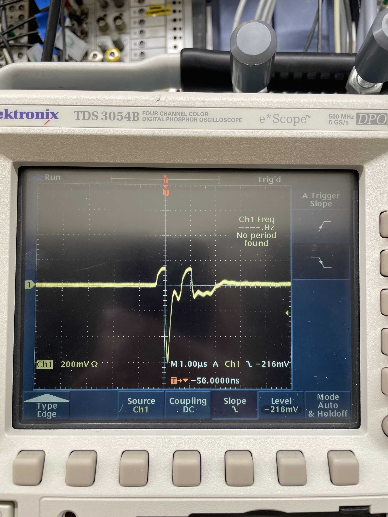
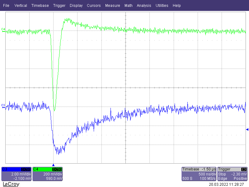
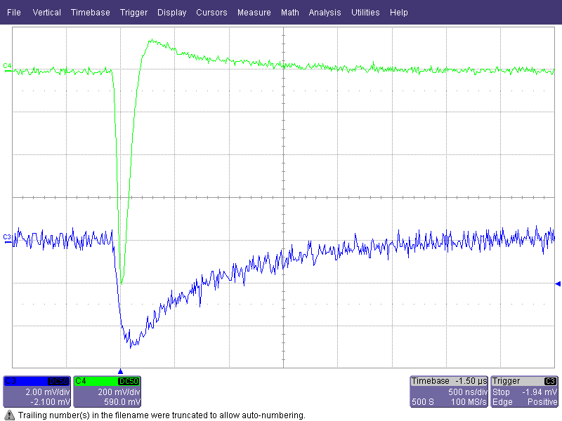
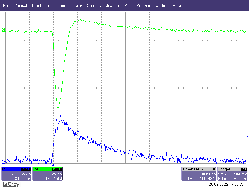
Cathodes are tested with generator. It is connected in FRS Messhuette. Generator produced bipolar analog signal, see Fig. 1. The signal is fed into the chain with cathodes. Output signal from cathode should look smth like this, see Fig.2.
If signal is missing, several things are possible:
Some connection is broken/loose. Very often it is so, go to the caves to check this.
Preamp is defect and should be replaced. Either preamp box can be removed from detector without opening it (possible with some MWPCs, e.g. MW11), or one has to take detector to the detector lab for repair (like it was done for MW82 in 2020).
Voltage supply for pream (+6V -12V) is broken.
Fig.1 Signal from generator.Fig.2 Signal from cathode if generator is fed to it.
Anodes are tested only with voltage on (and detectors should be filled with gas!). All detectors except the ones at S8 are equipped with 90Sr beta source. MW81 and MW82 can only be tested on cosmics.
Starting from some value of voltage (from 2 kV and up, different for each detector), detectors begin to generate noise. This can be traced by looking at the anode current. During normal operation and with no beam the current is zero. For example, MW82 generates no noise up to 2 kV on anode (with 0.0 uA current), and starting from 2.1 kV (abrupt increase of current to 2 uA) one can see constant noise signals. If the voltage is too high, one can see also sparks. On the scope those look like huge saturated signals. If sparks start to appear, reduce the voltage immediately!
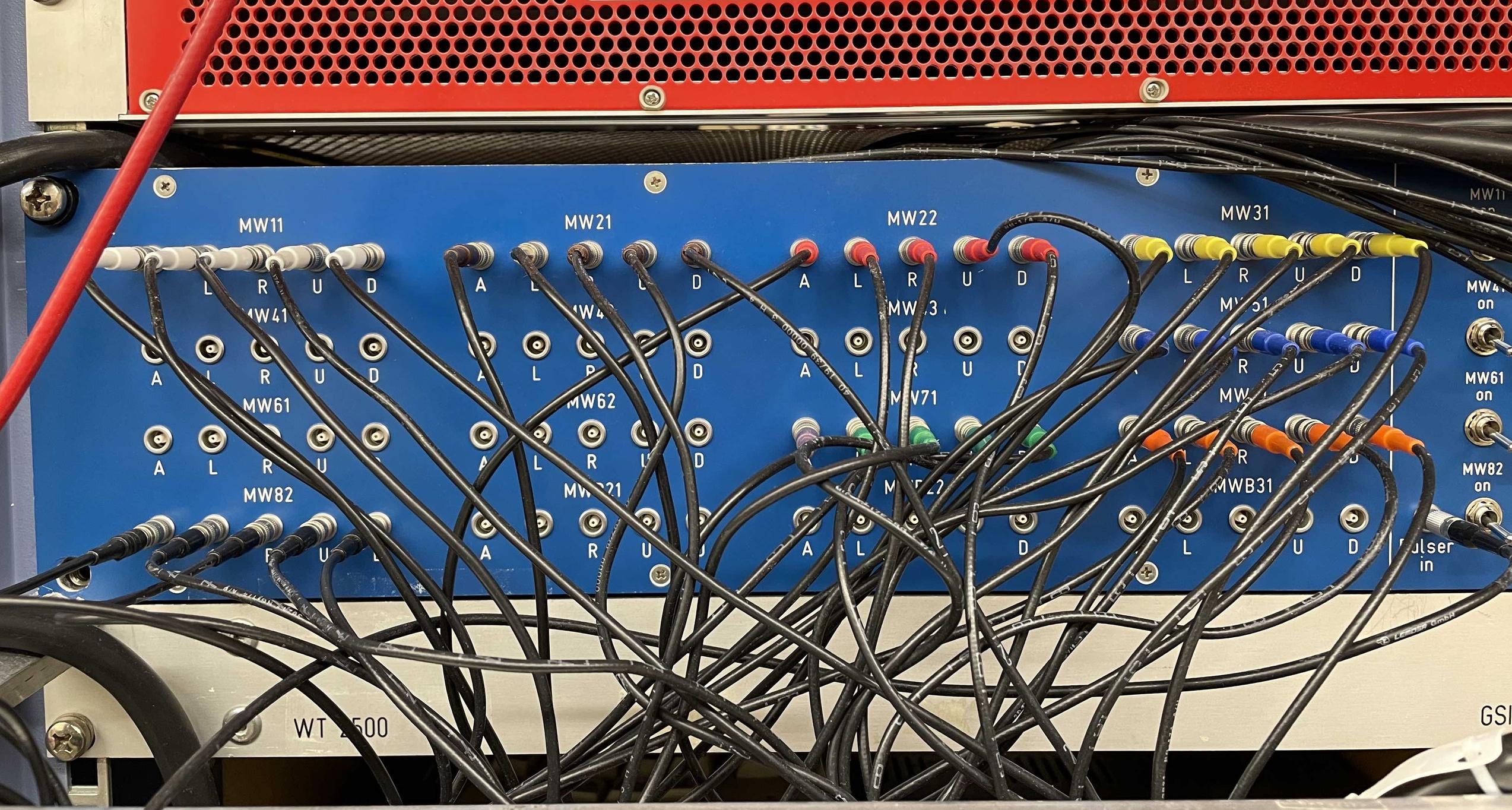
Where to find MWPC electronics in Messhuette
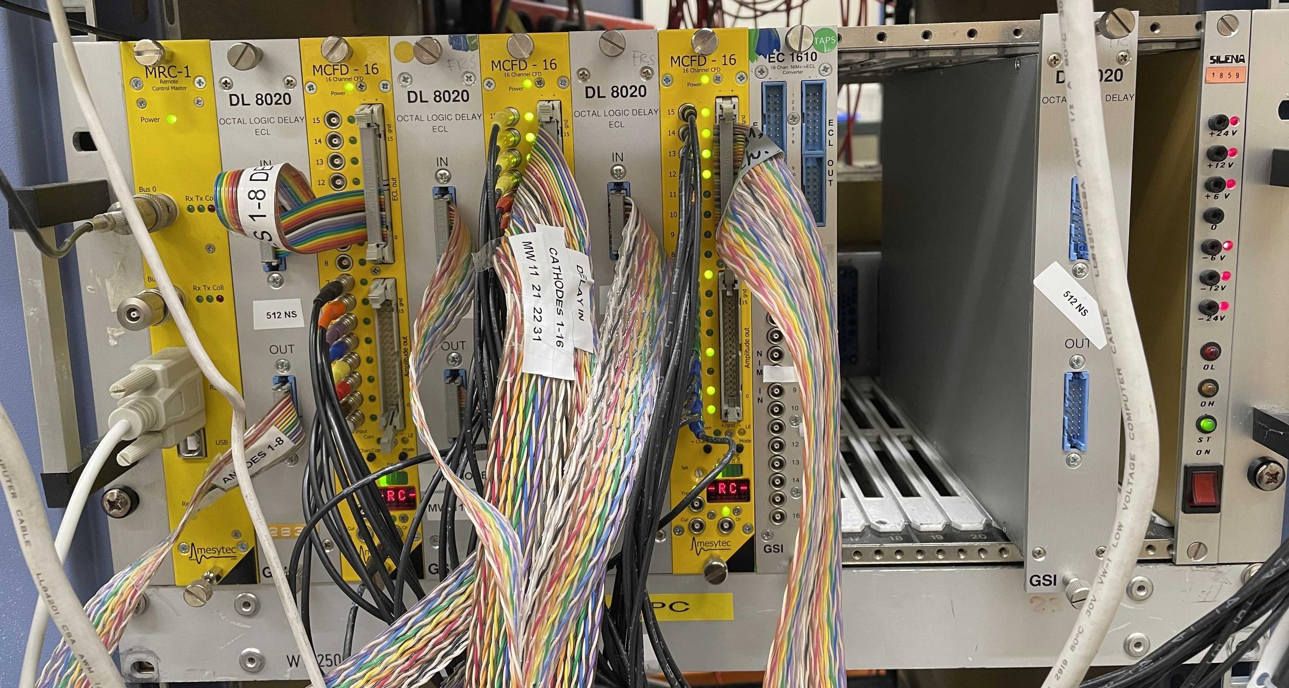
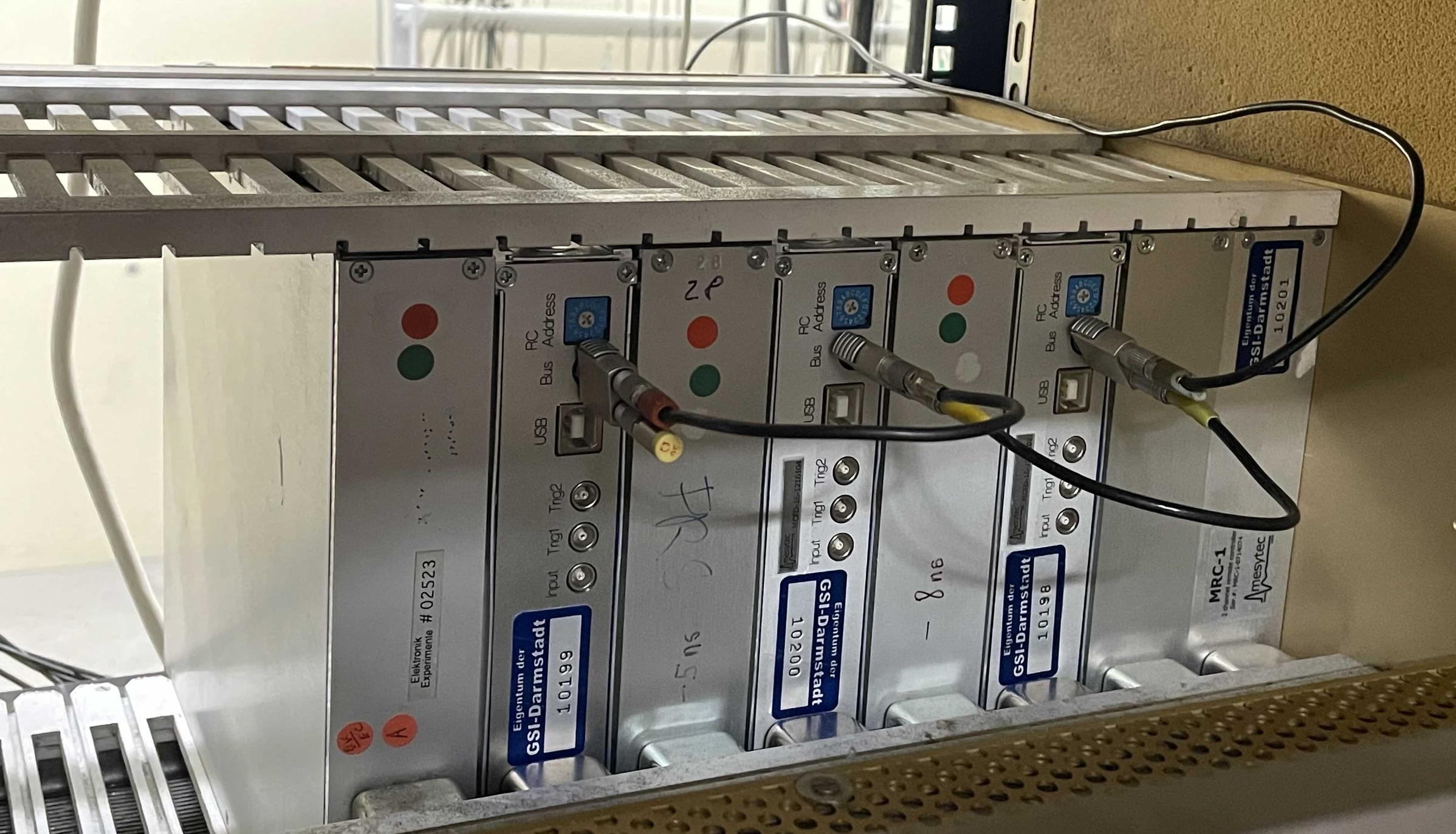
The patch panel of the MWPCs and all the corresponding electronic modules are located in the electronic room of the Messhuette, see the Figures below.
Fig.3 Panel with output analog signals from MWPCs.Fig.4 NIM crate with three Mesytec CFDs (MCFD-16), one Remote Control module (MRC-1) and three delay modules* (DL8020). Flat cabels with logic signals from anodes and cathodes go to TDCs in one of the vme crates of FRS (called vme_user, the one with r4l-63 processor). Fig.5 Back side of the NIM crate. Make sure connection between MRC-1 and CFDs is there!
*Delay is introduced to the logic signals from all the anodes and 11, 21, 22, 31 cathodes. Those signals require to be delayed because the corresponding TDC (V775, geo 8) is configured for common start. Logic signals from 51, 71, 81, 82 cathodes are sent to the TDC (V775, geo 9) configured for common stop. The mapping of the TDCs can be found under profi in e.g. /lynx/Lynx/frs/usr/profi/mbsrun/sec_expfeb21/vme_user/mapping
Web page of MWPCs by Hemlut Weick
Can be found here, but it is partly not up-to-date.