
Here is information contributed by my brother Mark on how to adapt a Apollo 19" 1024x800 color monitor for use on a PC.
DISCLAIMER: The circuit presented here has destroyed video cards during testing. Use at your own risk!
OVERVIEW
This circuit allows a PC to display video on an Apollo 19" color monitor, P/N 008398-001. These monitors are fixed frequency, 1024x800, 60 Hz vertical refresh, sync-on-green. Horizontal and Vertical sync are active low. Many PC video cards will support 1024x768 resolution, which is generally close enough that the monitor can sync to the video signal produced. The number of colors supported by the video card is unimportant as the monitor is analog and will support 16/256/16K or greater colors.
This circuit has not been tried on the higher resolution 1280x1024 Apollo monitors which have a different horizontal and vertical scan frequency.
ADVANTAGES
DISADVANTAGES
CIRCUIT DESCRIPTON
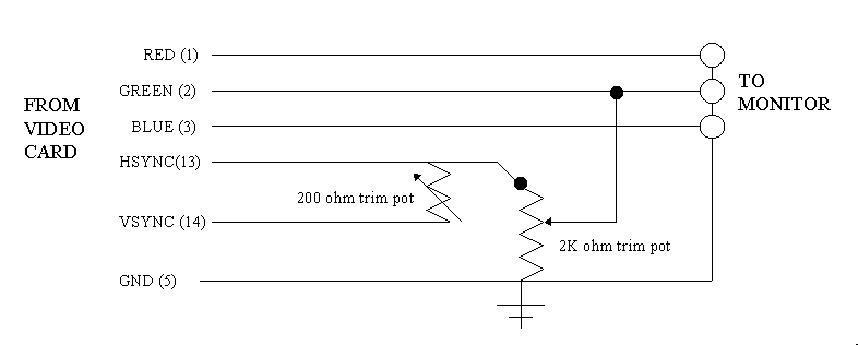
The circuit results in an "wired-OR" of the Horizontal and Vertical sync signals to produce a composite sync signal. Not all video cards can handle this. Then a trim-pot is used as a resistor divider to tap off 0.5 volts of composite sync needed by the monitor. The composite sync signal is then summed with the green video signal.

A SAMPLE ADAPTOR
One method of construction is seen below. It involves taking a PC slot cover blank and mounting three female BNC connectors to it. A short cable connects to the video card of the PC and passes the signals back to the BNC's mounted on the bracket. The video is supplied to the monitor on three equal lengths of 75 ohm coax with BNC connectors on each end. Note: Keep video cable coax lengths identical and less than 4 feet long.

Another method would be to build a cable bundle with 3 BNC connectors on one
end and a 15 pin male VGA connector at the other end. The passive components
would be bundled inside the cable itself.

Pin reference looking into the pins of a standard 15 pin VGA connector.
SAMPLE PARTS LIST
Here's a sample screen shot as captured by a Wincast PCI TV-Tuner card
off the 19" Apollo color monitor driven by Windows 95.

If you point the camera source at the monitor which is displaying the camera
output you get this "infinity" look.

SETUP and TESTING
You must have a monitor cable of displaying VGA resolution to boot up your system until everything is setup and working properly. Afterwards you should no longer need the VGA monitor.
With the VGA monitor attached and the cover off of your machine, setup your windows or linux video to:
With your finger on the major video chip of the vide card, reboot and get an idea of how hot the video chip will be under normal circumstances.
BEFORE connecting the video adapter, adjust the 2K trimpot center tap to ground to a resistor value of 1.5K Ohms. Then leave this alone. Do not adjust this trimpot while powered up or in use.
Next, use the 200 Ohm trimpot as a variable resistor to attenuate the vertical sync. Set this to almost no resitance, around 5 to 10 Ohms.
Connect the adapter circuit, BUT LEAVE THE MONITOR DISCONNECTED. Then boot up.
If possible, look at the signals with an oscilloscope. The horizontal line time should be around 20 uS (microseconds). If not, your video timing is incorrect and the monitor will most likely not sync up.
With normal operation, the horizontal and vertical sync signals coming directly from your video card should be high (4-5 volts) most of the time. If not, your video card is not generating the negative sync polarity on both H and V signals.
Shut down, attach the color monitor, and reboot. While booting, rest a FINGER on the VIDEO CHIP of your video card. If it get's too hot, shutdown your system immediately. If it's temperature is OK, then adjust the 200 Ohm trimpot for best signal sync-up. Again, do not adjust the 2K trimpot live.
GOOD LUCK!
