OTRON - a remote-controlled laser beam distribution system
Dariusz Miskowiec, GSI Darmstadt, Germany
New Focus opto-mechanics was used to control the laser beam for calibration of a particle physics detector at CERN, Switzerland. In this note I briefly describe the system, the difficulties encountered, and the ways to overcome them.
CERES is a particle physics experiment operating at the European Nuclear Physics laboratory CERN in Geneva, Switzerland. Charged particles produced in high energy ion collisions are detected using gas ionization chambers. A laser beam ionizes gas similarly as the particles do, and thus can be used for calibration of the particle detectors. The CERES setup, including the new large cylindrical Time Projection Chamber detector (TPC), is shown in Fig. 1. The laser beam is sent about 12 m along the wall, then it is reflected toward the cylinder axis, then once again reflected following the axis upstream. From there the beam is sent radially toward an azimuthal sector of the detector. Finally, one, two, or seven semi-transparent mirrors direct the laser beam through quartz windows into the sensitive volume of the particle detector.
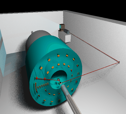
Figure 1. Schematic view of the CERES experiment at CERN SPS. The laser system is used to simulate particle tracks in the Time Projection Chamber (large blue cylinder). During operation the area cannot be accessed because of radiation. The laser and a linux PC are placed in the far corner because of magnetic field. Please disregard the laser beam shadow...
Following aspects had to be considered when designing the system.
- During a typical experiment, accelerator beam particles arrive in 5 second spills, followed by 14 second pauses. During the spill no material is allowed to be on the cylinder axis. The pause is the time when the laser calibration is done. Thus, within 14 seconds, one needs to
- flip the mirrors in
- switch the laser on
- switch to the next azimuthal sector of the detector by rotating the central mirror
- adjust position
- send several laser pulses accompanied by the detectors data acquisition trigger
- switch the laser off
- flip the mirrors out of the particle beam.
- The system should work automatically. Human interventions are impossible because of radiation.
- The absolute position of the rays injected into the detector needs to be known to 200-300 microns. All beam diagnostics must be done before the rays enter the detector because no additional material should be placed at the opposite end of it.
- The presence of strong magnetic field does not allow to use any electrical motors.
- Not too much space is available so all elements have to be rather compact.
The laser is placed in a far corner of the experiment zone to protect it from the magnetic field. The same place was chosen for the Linux PC which controls the laser and the mirrors and reads out the position sensitive diodes.
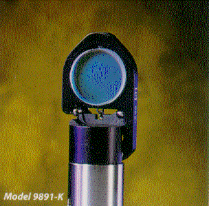
The optics located on the cylinder axis, consisting
of two mirrors, one quarter-wave plate, and one position
sensitive diode, can be flipped in and out. The magnetic field does not allow
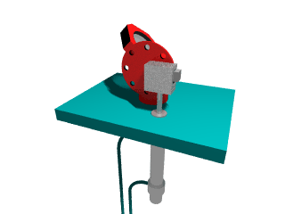
to use the New Focus motorized flippers. Instead, we used standard flippers
controlled by pneumatic actuators (Fig. 2).
Figure 2. Left: New Focus manual flipper. Right: flipper equipped with a pneumatic actuator. Click on the picture for animation.
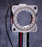
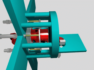
To switch between azimuthal sectors of the detectors we used the New Focus rotary stage (Fig. 3). This stage is relatively small and works in magnetic field. A flipper, mounted on the stage, allowed to flip the mirror in and out independently on the azimuthal orientation.
Figure 3. New Focus rotary stage (left) and its use in the rotating mirror setup of the laser calibration system of CERES (right). Click on the picture for animation.
The unique feature of the picomotor actuators of New Focus are their insensitivity to magnetic field. Also, they are smaller than the usual stepper motors. The disadvantage is their poor step reproducibility. In our system the result of each adjustment was controlled by monitoring the beam position with position sensitive diodes. Their information was used by the Linux PC to adjust mirrors such to place the beam in the required position. The software had learning ability so after letting the program run for half an hour or so it would know quite well how many pico-steps were needed to approximately reach the wanted beam position. One or two more steps would be enough to adjust the beam to 100 microns.
The system ran successfully for one week (without switching from sector to sector) in parallel with the particle physics data taking in 1999. moreover, in 1999 and in 2000 several dedicated laser runs were performed in which the detector was scanned by shooting about 1000 laser pulses into each sector. The results were extensively used to improve the understanding of the detector.
Summarizing, using New Focus components we devised a fully automatic and a reliable laser beam distribution system for calibration of the CERES TPC detector. A short movie presenting the central part of the actual setup is available here.
