Laser system manual
October 5, 1999
1. Logging in
Login on pcceres7 (user ceres, standard password) and set display by
typing "setenv DISPLAY ...".
Start the laser control code by typing "laser-tcltk&". Start the
mirror control code by typing "manager-tcltk&". Start the diodes monitor
code by typing "diodes-tcltk" (without ampersand - it is easier to kill
it if something goes wrong). Make sure that the server process
diodes_shmwriter is running.
2. Operating laser (laser-tcltk)
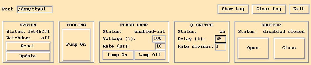
Press "Pump On" to start cooling. Set voltage to 100, rate between 1
and 10 Hz, Delay to 70, Rate divider to 1. Press "Lamp On" to turn on the
flash lamp. Press "Open" to open the shutter. Adjust laser energy by changing
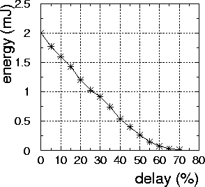
the Q-switch delay between 20 and 75. Lower delays give higher energy
and less energy fluctuations. Higher delays give a better beam profile.
To turn off the laser, press "Close" to close the shutter, then press
"Lamp Off" to switch off the flash lamp, and finally press "Exit" or press
the <Escape> key to quit laser-tcltk.
3. Moving mirrors (manager-tcltk)
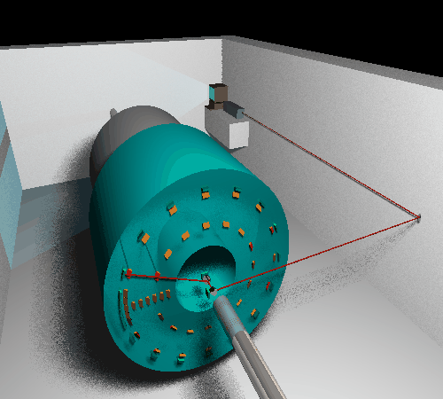 Mirror 1 is on the small platform on the Jura wall of the zone. It
reflects the beam by 90 degrees to the right, i.e. toward the accelerator
beam axis. Mirror 2 is on the TPC axis, 20 cm downstream from the backplate.
It reflects the beam by 90 degrees to the right, i.e. toward the target.
Rotary stage 1 is on the center of the TPC backplate. The mirror mounted
on this stage reflects the beam by 90 degrees outwards. By rotating this
stage one changes the phi-coordinate of the laser beam.
Mirror 1 is on the small platform on the Jura wall of the zone. It
reflects the beam by 90 degrees to the right, i.e. toward the accelerator
beam axis. Mirror 2 is on the TPC axis, 20 cm downstream from the backplate.
It reflects the beam by 90 degrees to the right, i.e. toward the target.
Rotary stage 1 is on the center of the TPC backplate. The mirror mounted
on this stage reflects the beam by 90 degrees outwards. By rotating this
stage one changes the phi-coordinate of the laser beam.
The manager-tcltk window is shown below. In the following
the subwindows will be briefly described.
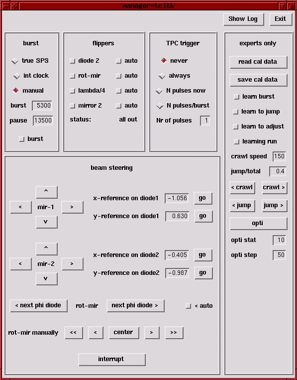
burst
Select "true SPS" burst if you want to move the mirrors in- and out-of
beam axis burst by burst. Select "manual"
if mirrors are allowed to stay in beam all the time.
flippers
The four flippers carry MIR 2, lambda/4, Rotating Mirror, and diode
2. Selecting a flipper button means inserting the given item into
the beam. Selecting "auto" will mean flipping the mirrors in during the
burst pause and out during the burst. Flippers should be in when laser
beam is being used, and out when the particle beam is coming. This is to
avoid background in the TPC; the mirrors themself will not be damaged by
the particle beam. The behaviour of the flippers can be watched on the
TV monitor, same as the one showing the SPS burst status, but on channel
0 instead of 1.
trigger
If "always" is selected, each laser pulse will send a pulse to the experiment's
trigger system. The meaning of the other buttons should be obvious.
beam steering
The MIR 1 and MIR 2 mirrors should only be adjusted by an expert. The
Rotating Mirror allows to shoot the laser beam radially towards different
TPC sectors. The orientation of the Rotating Mirror can be changed by pressing
buttons "< next phi diode" and "next phi diode >". The mirror
can also be moved manually (buttons "<<", "<", ">", and ">>"),
and the laser beam can be centered on a diode (button "center").
A typical calibration setting is "manual" burst ,"burst " not selected,
all flippers in, trigger "always".
A typical monitoring setting is "true SPS" burst, all flippers
"auto", trigger 1 per burst, rot-mir "auto".
4. Using diodes to monitor the beam position (diodes-tcltk)
The diodes detect incident laser beam and yield the position to better
than 0.1 mm. Each diode has the size of 10x10 mm^2. The diodes are usually
located behind the mirrors. The mirrors are partially reflecting. The transmitted
beam hits the diode. The particular locations are as follows
1 - behind MIR 1
2 - behind Rotating Mirror
3 - rotating together with Rotating Mirror
4 - sector 0
5 - sector 1
6 - sector 2
7 - sector 3
8 - sector 4
9 - sector 5
10 - sector 6
11 - sector 7
12 - sector 8a
13 - sector 8c
14 - sector 8e
15 - sector 8g
16- sector 8i
17 - sector 9
18 - sector 10
19 - sector 11
20 - sector 12
21 - sector 13
22 - sector 14
23 - sector 15
In diodes-tcltk the position of the laser beam on each diode is represented
by a blue spot. The spot size is related to beam energy (not to beam diameter).
The spot becomes red if one of the four diode channels has overflow. In
this case the position information is unreliable. The window "Diode ..."
shows the diode data averaged over all events contained in the buffer.
The three numbers are x,y (in mm) and intensity (in ADC channels). "Clear
buffer" clears the event buffer. "Save buffer" writes the average positions
of all diodes on file diodes-tcltk.dat.
Dariusz Miskowiec