From Nand to Tetris
Lecture Notes & Comments
“From Nand to Tetris in 12 steps” 1, Shimon Schocken, 2007, Google Talks
- Based on the book The Elements of Computer Systems 2
- Widespread adaptation of this material by others 3 4
- Nand to Tetris projects 1-12 5 used along the course
What is this about?
- Demystify the integrated function of computer systems
- Building a general purpose computer system from the ground up, hardware and software…
- …starting from basic NAND gates to a hardware platform
- …build in a simulator …up to the complete (virtual) Hack computer 6
- Design a software environment beginning with machine language…
- …to a compiler for the Jack programming language
- …as foundation for a simple operating system
Part 1
“From Nand to Tetris Part 1” 7, Shimon Schocken and Noam Nisam, 2018, Youtube
Unit 0
The Road Ahead
Introduction to computer science typically top-down…
- …starts with a “Hello World” program (very high layer of abstraction)
- …printing a simple text on a computer screen
- …focuses on the implementation details in a programming language
- …omits any details about all underlying layers of abstraction
- Don’t worry about the “how”, only about the “what”
Layers of abstraction…
- …compartmentalise knowledge & functionality in layers
- …clearly defined interfaces to top and bottom layers
- …user an abstraction layer without knowledge of the internals
- …complex systems create by many “simpler” layers of abstraction
NAND to Tetris abstraction layers (top to bottom):
- Software hierarchy:
- Program written by a humane in a High Level Language compiled to…
- …VM Code further translated to hardware specific Low Level Code…
- Hardware platform:
- …this assembler code is used to run on a Computer Architecture
- …build from components CPU, RAM, chipset…
- …composed from elementary Logic Gates
Course builds a functioning computer layer by layer, bottom-up …
- …gain experience implementing abstractions
- …step by step working thru complexity of building a computer
From Nand to Hack
Electrical engineering (EE) not part of computer science…
- …EE builds computer hardware from semi-conductor electronics
- …course not concerned with details of hardware construction
- …course starts by using the basic NAND logic gate
Use of combinational logic to build other logic gates like AND and OR…
- …from there us combinational and sequential logic to build registers, memory and a CPU
- …followed by digital design to create a complete computer architecture called Hack
- …with an assembler to provide the low level code interface
Hardware simulator used to design and debug in the process
Example XOR chip abstraction with following logic table:
a | b | out
--|---|----
0 | 0 | 0
0 | 1 | 1
1 | 0 | 1
1 | 1 | 0- …student asked to design a chip diagram from other basic gates (build before)
- …specify chips behavior using a Hardware Description Language (HDL)
- …use test scripts to verify correct behavior of a chip in the simulator
CHIP Xor {
  IN a, b;
  Out out;

  PARTS:
  Not (in=a, out=nota);
  Not (in=b, out=notb);
  And (a=a; b=notb; out=aAndNotb);
  And (a=nota, b=b, out=notaAndb);
  Or  (a=aAndNotb, b=notaAndb, out=out);
}
Projects structure to build the Hack computer:
- Elementary logic gates
- Arithmetic logic unit (ALU)
- Registers & Memory
- Write programs in Hack machine language
- Computer architecture
- Develop an assembler
From Hack to Tetris
Goal for part 2 of “From Nand to Tetris”
- …based on the Hack assembly language developed in part 1
- …build a compiler for the Jack high-level programming language
- …use Jack to implements a standard library and operating system
Project 0
Setup the developed environment…
- …official Nand2Tetris web-page 8 hosts the software suite
- …download the
nand2tetris.ziparchive from https://www.nand2tetris.org/software - …can be used freely under the terms of the GNU GPL (General Public License)
- …extract the archive (…put the
nand2tetris/directory under version control)
Sub-directories…
tools/contains*.shscripts to start software tools- Hardware simulator …tests logic gates and chips implemented in the HD
- CPU emulator
- …emulates the operation of the Hack computer system
- …run programs in the Hack machine language
- VM emulator
- …emulates the operation of our virtual machine
- …run programs written in the VM language
- Assembler …translates programs from the Hack assembly language to Hack binary code
- Jack compiler …translates programs written in Jack to run on the VM emulator
- OS …implementation of all the OS services
projects/directory …files for projects 1 to 13 …contents will be modified during course
# Set the executable bit on all scripts…
chmod +x tools/*.sh

# Start the hardware simulator (for example)
./tools/HardwareSimulator.sh
Unit 1
Boolean Logic
What is boolean logic?
- …system of logical operations …that uses
0/1(on/off, true/false, no/yes) …boolean value - …fundamental concept in computer science …extensively used in digital electronics …used to design and implement digital circuits
- …basic logic operations combined to more complex logical expressions …allows to build sophisticated decision-making and problem-solving
Boolean operations based on 0/1
- Example
- …conjunction
x AND y…true if all the input values are true - …disjunction
x OR y…true if at least one of the input values is true - …negation …inversion
NOT x…returns the opposite of the input value
- …conjunction
- …finite number of inputs …allows to know all possible values
Truth-table shows all possible combinations of inputs and their corresponding outputs…
- …used to design, analyze, and verify the behavior of digital systems
- …typically consists of two parts …input columns (possible input values) …output column for each possible combination of input values
Truth-table for NAND (NOT-AND) gate:
| a | b | out |
|---|---|---|
| 0 | 0 | 1 |
| 1 | 0 | 1 |
| 0 | 1 | 1 |
| 1 | 1 | 0 |
Boolean identities
- Commutative laws
(x AND y) = (y AND x),(x OR y) = (y OR x) - Associative laws
(x AND (y AND z)) = ((x AND y) AND z)(same forOR) - Distributive laws
(x OR (y AND z)) = (x OR y) AND (x OR z), etc. - De Morgan laws
NOT(x AND y) = NOT(x) OR NOT(y), etc.
Boolean algebra …simplification of boolean expressions…
NOT(NOT(x) AND NOT(x OR y))           # De Morgan law
NOT(NOT(x) AND (NOT(x) AND NOT(y)))   # Associative law
NOT((NOT(x) AND NOT(x)) AND NOT(y))   # Idempotence law
NOT(NOT(x) AND NOT(y))                # De Morgan law
NOT(NOT(x)) OR NOT(NOT(y))            # Double negation law
x OR y
Boolean Functions
Construct boolean functions from primitive operations…
- Start from a truth tables and write a boolean function
- …write a dedicated function for each row with a value of
1 - …combine all functions with
OR…use boolean algebra to simplify - …find the shortest …most efficient boolean function …NP problem
Any boolean functions can be represented with only NAND
NOT(x)    = (x NAND x)
(x AND y) = NOT(x NAND y)
…therefore a complete compute can be build using only NAND gates
Logic Gates
Aka digital logic gates:
- …boolean logic used to design digital gates, which are the basic building blocks of digital circuits (aka logic circuits)
- …the term “gate” in digital electronics comes from the idea of controlling the flow of electrical signals …similar to how mechanical gates control the flow of materials or energy
- Logic circuits used to perform specific tasks, such as:
- …control functions …counters
- …arithmetic operations
- …data storage (flip-flops)
- …digital signal processing
- …encoders & decoders
- …multiplexers & demultiplexers
Elementary gates are the basic building blocks of digital circuits
- …three elementary gates
NOT,AND,OR - …simplest forms of digital gates that perform a single logical operation
- Combining these gates in different way to create more complex logical operations… such as
NAND,NOR,XOR, andXNORgates
Composite gates are build from combinations of elementary gates
- Gate interface …abstraction for the user …functionality of a gate
- Gate implementation …internal construction of the gate
- …one interface can have multiple implementations
- …with different complexity …energy consumption …cost
Functional specification of elementary gates…
if (a==1 and b==1) then out=0 else out=1     # NAND
if (a==1 and b==1) then out=1 else out=0     # AND
if (a==1 or  b==1) then out=1 else out=0     # OR
if (in==0) then out=1 else out=0             # NOT
Hardware Description
Complete description of a gates functionality
/** Xor gate: out = (a And Not(b)) Or (Not(a) And b)) **/

CHIP Xor {
    IN a, b;
    OUT out;
    PARTS:
    Not (in=a, out=nota);
    Not (in=b, out=notb);
    And (a=a, b=notb, out=aAndNotb);
    And (a=nota, b=b, out=notaAndb);
    Or (a=aAndNotb, b=notaAndb, out=out);
}
HDL (Hardware Description Language) file textual description of a gate diagram
- …functional/declarative language
- …use by a hardware simulator
- …order of HDL statements insignificant
- …before using a gate, you must know its interface
Not(in=, out= )And(a=, b=, out= )Or(a=, b=, out= )
Common HDL: VHDL, Verilog
Hardware Simulation
Simulator 9 used to evaluate HDL
Write HDL declaration (or load an HDL file)
- …interactively …enter values
0/1- …into the chips input pins
- …evaluate output & internal pins
- Play around with the simulator:
Not.hdl
/**
 * Not gate:
 * if (in) out = 0, else out = 1
 */
CHIP Not {
    IN in;
    OUT out;

    PARTS:
    Nand(a=in, b=in, out=out);
}
Test script provided…
Not.hdl
load Not.hdl
output-list in out;
set in 0, eval, output;
set in 1, eval, output;
…generates an output file and evaluates correctness to a compare file
Not.cmp
|in |out|
| 0 | 1 |
| 1 | 0 |
Hardware construction projects
- …system architects
- …user level specification
- …decides which chips are needed …chip API …test scripts …compare files
- …developers …build chips based on that information
Hack computer requires 30 different chips
Multi-bit Buses
Array of bits …manipulated together
- …such groups are called bus
- …HDL provides a convenient notation for handling buses
Use of a bus for example in a 16-bit adder with following interface:
Add16.hdl
CHIP Add16 {
  IN a[16], b[16];
  OUT out[16];

  PARTS:
  // Implementation missing
}
Square [ ] to represent groups of bits …manipulating entire buses is implicit:
Add3Way16.hdl
CHIP Add3Way16 {
  IN first[16], second[16], third[16];
  OUT out[16];
  PARTS:
    Add16(a=first, b=second, out=temp);
    Add16(a=temp, b=third, out=out);
}
…working with individual bits in a bus
And4Way.hdl
CHIP And4Way {
  IN a[4];
  OUT out;
  PARTS:
    AND(a=a[0], b=a[1], out=t01);
    AND(a=t01, b=a[2], out=t012);
    AND(a=t012, b=a[3], out=out);
}
And4.hdl
CHIP And4 {
  IN a[4], b[4];
  OUT out[4];
  PARTS:
    AND(a=a[0], b=b[0], out=out[0]);
    AND(a=a[1], b=b[1], out=out[1]);
    AND(a=a[2], b=b[2], out=out[2]);
    AND(a=a[3], b=b[3], out=out[3]);
}
Buses can be compose from and broken into sub-buses:
IN lsb[8], msb[8], …

Add16(a[0..7]=lsb, a[8..15]=msb, b=…, out=… );
Add16(…, out[0..3]=t1, out[4..15]=t2);- …overlap of sub-buses are allowed
- …width of internal pins deduced automatically
- …
false/truemay be used as bus of any width
Project 1
NAND is given… build 15 gates from that
- …these gates widely used
- …all logic gates required to build the Hack computer
- Elementary logic …Not, And, Or, Xor, Mux, DMux
- 16-bit variants …Not16, And16, Or16, Mux16
- Multi-way variants …Or8Way, Mux4Way16, Mux8Way16, DMux4Way, DMux8Way
Multiplexer …gate with a sel (select)
- …pseudo code:
if (sel==0) then out=a else out=b - …2-way multiplexer enables selecting one of two possible inputs
- …fundamental operations used in digital design and communication networks
- Using mux logic to build a programmable gate:
AndMuxOr…selects betweenAndorOrgate function- …pseudo code:
if (sel==0) then out = (a And b) else out = (a Or b)
AndMuxOr.hdl
CHIP AndMuxOr {
  IN a, b, sel;
  OUT out;

  PARTS:
  And (a=a, b=b, out=andOut);
  Or  (a=a, b=b, out=orOut);
  Mux (a=andOut, b=orOut, sel=sel, out=out);
}
Demultiplexer …inverse of multiplexer …sel used to select output channel
- …pseudo code …2-way:
if (sel==0) then {a,b}={in,0} else {a,b}={0,in} - …single input distributed into on of two possible channels
Use-cases …interleave multiple messages on single shared communication line
Solution to Project-1:
CHIP Not {
    IN in;
    OUT out;

    PARTS:
    Nand (a=in, b=in, out=out);
}
CHIP And {
IN a, b;
OUT out;
PARTS:
Nand (a=a, b=b, out=temp);
Not (in=temp, out=out);
}CHIP Or {
IN a, b;
OUT out;
PARTS:
Not (in=a, out=nota);
Not (in=b, out=notb);
And (a=nota, b=notb, out=tmp);
Not (in=tmp, out=out);
}CHIP Xor {
IN a, b;
OUT out;
PARTS:
Not (in=a, out=nota);
Not (in=b, out=notb);
And (a=a, b=notb, out=aAndNotb);
And (a=nota, b=b, out=notaAndb);
Or (a=aAndNotb, b=notaAndb, out=out);
}CHIP Mux {
IN a, b, sel;
OUT out;
PARTS:
Not (in=sel, out=notSel);
And (a=a, b=notSel, out=tmpA);
And (a=b, b=sel, out=tmpB);
Or (a=tmpA, b=tmpB, out=out);
}CHIP DMux {
IN in, sel;
OUT a, b;
PARTS:
Not (in=sel, out=notSel);
And (a=in, b=notSel, out=a);
And (a=in, b=sel, out=b);
}CHIP Not16 {
IN in[16];
OUT out[16];
PARTS:
Not (in=in[0], out=out[0]);
Not (in=in[1], out=out[1]);
Not (in=in[2], out=out[2]);
Not (in=in[3], out=out[3]);
Not (in=in[4], out=out[4]);
Not (in=in[5], out=out[5]);
Not (in=in[6], out=out[6]);
Not (in=in[7], out=out[7]);
Not (in=in[8], out=out[8]);
Not (in=in[9], out=out[9]);
Not (in=in[10], out=out[10]);
Not (in=in[11], out=out[11]);
Not (in=in[12], out=out[12]);
Not (in=in[13], out=out[13]);
Not (in=in[14], out=out[14]);
Not (in=in[15], out=out[15]);
}CHIP And16 {
IN a[16], b[16];
OUT out[16];
PARTS:
And (a=a[0], b=b[0], out=out[0]);
And (a=a[1], b=b[1], out=out[1]);
And (a=a[2], b=b[2], out=out[2]);
And (a=a[3], b=b[3], out=out[3]);
And (a=a[4], b=b[4], out=out[4]);
And (a=a[5], b=b[5], out=out[5]);
And (a=a[6], b=b[6], out=out[6]);
And (a=a[7], b=b[7], out=out[7]);
And (a=a[8], b=b[8], out=out[8]);
And (a=a[9], b=b[9], out=out[9]);
And (a=a[10], b=b[10], out=out[10]);
And (a=a[11], b=b[11], out=out[11]);
And (a=a[12], b=b[12], out=out[12]);
And (a=a[13], b=b[13], out=out[13]);
And (a=a[14], b=b[14], out=out[14]);
And (a=a[15], b=b[15], out=out[15]);
}CHIP Or16 {
IN a[16], b[16];
OUT out[16];
PARTS:
Or (a=a[0], b=b[0], out=out[0]);
Or (a=a[1], b=b[1], out=out[1]);
Or (a=a[2], b=b[2], out=out[2]);
Or (a=a[3], b=b[3], out=out[3]);
Or (a=a[4], b=b[4], out=out[4]);
Or (a=a[5], b=b[5], out=out[5]);
Or (a=a[6], b=b[6], out=out[6]);
Or (a=a[7], b=b[7], out=out[7]);
Or (a=a[8], b=b[8], out=out[8]);
Or (a=a[9], b=b[9], out=out[9]);
Or (a=a[10], b=b[10], out=out[10]);
Or (a=a[11], b=b[11], out=out[11]);
Or (a=a[12], b=b[12], out=out[12]);
Or (a=a[13], b=b[13], out=out[13]);
Or (a=a[14], b=b[14], out=out[14]);
Or (a=a[15], b=b[15], out=out[15]);
}CHIP Mux16 {
IN a[16], b[16], sel;
OUT out[16];
PARTS:
Mux (a=a[0], b=b[0], sel=sel, out=out[0]);
Mux (a=a[1], b=b[1], sel=sel, out=out[1]);
Mux (a=a[2], b=b[2], sel=sel, out=out[2]);
Mux (a=a[3], b=b[3], sel=sel, out=out[3]);
Mux (a=a[4], b=b[4], sel=sel, out=out[4]);
Mux (a=a[5], b=b[5], sel=sel, out=out[5]);
Mux (a=a[6], b=b[6], sel=sel, out=out[6]);
Mux (a=a[7], b=b[7], sel=sel, out=out[7]);
Mux (a=a[8], b=b[8], sel=sel, out=out[8]);
Mux (a=a[9], b=b[9], sel=sel, out=out[9]);
Mux (a=a[10],b=b[10],sel=sel, out=out[10]);
Mux (a=a[11],b=b[11],sel=sel, out=out[11]);
Mux (a=a[12],b=b[12],sel=sel, out=out[12]);
Mux (a=a[13],b=b[13],sel=sel, out=out[13]);
Mux (a=a[14],b=b[14],sel=sel, out=out[14]);
Mux (a=a[15],b=b[15],sel=sel, out=out[15]);
}CHIP Or8Way {
IN in[8];
OUT out;
PARTS:
Or (a=in[0],b=in[1], out=w1);
Or (a=w1, b=in[2], out=w2);
Or (a=w2, b=in[3], out=w3);
Or (a=w3, b=in[4], out=w4);
Or (a=w4, b=in[5], out=w5);
Or (a=w5, b=in[6], out=w6);
Or (a=w6, b=in[7], out=out);
}CHIP Mux4Way16 {
IN a[16], b[16], c[16], d[16], sel[2];
OUT out[16];
PARTS:
Mux16 (a=a, b=b, sel=sel[0], out=w1);
Mux16 (a=c, b=d, sel=sel[0], out=w2);
Mux16 (a=w1, b=w2, sel=sel[1], out=out);
}CHIP Mux8Way16 {
IN a[16], b[16], c[16], d[16],
e[16], f[16], g[16], h[16],
sel[3];
OUT out[16];
PARTS:
Mux4Way16 (a=a, b=b, c=c, d=d, sel=sel[0..1], out=abcd);
Mux4Way16 (a=e, b=f, c=g, d=h, sel=sel[0..1], out=efgh);
Mux16 (a=abcd, b=efgh, sel=sel[2], out=out);
}CHIP DMux4Way {
IN in, sel[2];
OUT a, b, c, d;
PARTS:
DMux (in=in, sel=sel[1], a=w1, b=w2);
DMux (in=w1, sel=sel[0], a=a, b=b);
DMux (in=w2, sel=sel[0], a=c, b=d);
}CHIP DMux8Way {
IN in, sel[3];
OUT a, b, c, d, e, f, g, h;
PARTS:
DMux (in=in, sel=sel[2], a=w1,b=w2);
DMux (in=w1, sel=sel[1], a=w3,b=w4);
DMux (in=w2, sel=sel[1], a=w5,b=w6);
DMux (in=w3, sel=sel[0], a=a, b=b);
DMux (in=w4, sel=sel[0], a=c, b=d);
DMux (in=w5, sel=sel[0], a=e, b=f);
DMux (in=w6, sel=sel[0], a=g, b=h);
}Perspective & Material
Questions from the video…
- Build a computer from a gate other then NAND?
- Yes, using a NOR (not or) gate
- …or by using a suite of gates like AND, OR and NOT
- However NAND is cheap and accessible in production
- How to actually build a NAND gate?
- This is a question of micro electronics…
- Example of an NMOS based implementation of a NAND gate
- …uses two transistors in sequence
- …however implementation is not important for this lecture
- How does the HDL compares to “real” ones used in industry?
- …more complex …include high-level constructs like loops
- …include timers and clocks
- …more difficult to learn …steep learning curve
- How to build more complex circuits/chips?
- …matter of engineering …helper tools exists
- …for example a silicon compiler
- …however problems reduced to smaller modules and composed by humans
Building gates in electronics:
- Making logic gates from transistors, Ben Eater, YouTube
- SR Latch, Ben Eater, Youtube
Read about…
- George Boole work on boolean algebra
- Claude Shannon work on logic circuits
Unit 2
Slides 10 to support lecture 2 (book chapter 2)
Binary Numbers
What can we do with 0/1?
- n-bits - 2ⁿ possibilities (combinations)
- Use-case …represent numbers
- …any number can be represented with a sequence of bits
- …comparison to the decimal system from math in school
- …maximum number …2ⁿ-1
- Fixed word size …fixed number of bits to used (limited range of numbers)
- 8-bits
0000 0000to1111 1111…2⁸ = 256 - …negative numbers require one bit as prefix
- 8-bits
- Explains conversion between decimal and binary
Binary Addition
Binary numbers enable manipulation with gates…
- Addition + negative numbers → Subtraction & comparison
- Multiplication and divisions not realized in hardware → software
- Explains addition in the binary system …right-to-left …carry over …overflow
Rest of the unit …build an adder in hardware using elementary gates
- …half-adder …adds two bits
- …full-adder …adds three bits (including a carry bit)
- Multi-bit Adder …adds numbers of any length
Half-adder truth-table:
a  b  | sum  carry
------|------------
0  0  | 0    0
0  1  | 1    0
1  0  | 1    0
1  1  | 0    1
HDL interface for the half-adder chip:
HalfAdder.hdl
CHIP HalfAdder {
  IN a, b;
  OUT sum, carry;
  PARTS:
    // Implement
}
Full-adder truth-table:
a  b  c  | sum  carry
---------|-----------
0  0  0  | 0    0
0  0  1  | 1    0
0  1  0  | 1    0
0  1  1  | 0    1
1  0  0  | 1    0
1  0  1  | 0    1
1  1  0  | 0    1
1  1  1  | 1    1
Multi-bit adder → combination of full-adder chips …for example 16 for 16bit
Negative Numbers
One possibility …first (left) bit used as sign bit (not popular)
Two’s complement
- …negative number \(-x\) represented with \(2^{ⁿ}-x\)
- …positive numbers \(0…2^{n-1}-1\) …negative numbers \(-1…-2^{n-1}\)
- …additions in 2’s complement for free
- representation in modulo 2ⁿ …addition in modulo 2ⁿ
- Compute \(-x\) from input \(x\) with \(2^{n}-x=1+(2^{n}-1)-x\)
Example input 4 output -4:
 1111    # 2ⁿ-1
-0100    # 4 ...input
 ----
 1011
+0001    # +1
 ----
 1100    # 12, 16-4 in 2's complement ...output -4
Arithmetic Logic Unit
ALU …very important component of all general purpose computers
- …references “von Neumann” architecture
- ALUs compute functions on two inputs
- …out of multiple pre-defined arithmetic of logic functions
- …addition, multiplication, division, etc.
- …bitwise AND, OR, XOR, etc.
- …complexity of ALU …hardware/software trade-off
The Hack ALU (specific example focused on)
- Operates on two 16-bit 2’s complement values
- Outputs a 16-bit 2’s complements value
- Function selection set by six 1-bit inputs
- pre-setting x input
zx…if zx then x=0nx…if nx then x=!x
- pre-setting y input
zy…if zy then y=0ny…if ny then y=!y
- select between computation + or &
f…if f then out=x+y else out=x&y
- post-setting the output
no…if no then out=!out
- pre-setting x input
- Two control 1-bit values
zr,ngif out==0 then zr=1 else zr=0if out<0 then ng=1 else ng=0
Computers one out of 18 functions
0 1 -1 x y !x !y -x -y x+1 y+1 x-1 y-1 x+y x-y y-x x&y x|yEasy to implement…
- Set 16-bit values to
0000000000000000 - Set 16-bit values to
1111111111111111 - Negate a 16-bit value (bit-wise)
- Compute
+or&on two 16-bit values
Project 2
Build a family of combinational chips:
HalfAdder.hdl
CHIP HalfAdder {
  IN a, b;
  OUT sum, carry;
  PARTS:
  And (a=a, b=b, out=carry);
  Xor (a=a, b=b, out=sum);
}- Tip: Can be build using two of the elementary gates
- …compare the truth-tables to select the appropriate gates
FullAdder.hdl
CHIP FullAdder {
  IN a, b, c;
  OUT sum, carry;
  PARTS:
  HalfAdder (a=a,  b=b,  sum=w1,  carry=c1);
  HalfAdder (a=w1, b=c,  sum=sum, carry=c2);
  Or        (a=c1, b=c2, out=carry);
}- Tip …build from two half-adders…
- …make sure to propagate carry from both halt-adders
- …note that the logic implies the both
HalfAdderwon’t have a carry at the same time
Add16.hdl
CHIP Add16 {
  IN a[16], b[16];
  OUT out[16];
  PARTS:
  HalfAdder (a=a[0],  b=b[0],         sum=out[0],  carry=c0);
  FullAdder (a=a[1],  b=b[1],  c=c0,  sum=out[1],  carry=c1);
  FullAdder (a=a[2],  b=b[2],  c=c1,  sum=out[2],  carry=c2);
  FullAdder (a=a[3],  b=b[3],  c=c2,  sum=out[3],  carry=c3);
  FullAdder (a=a[4],  b=b[4],  c=c3,  sum=out[4],  carry=c4);
  FullAdder (a=a[5],  b=b[5],  c=c4,  sum=out[5],  carry=c5);
  FullAdder (a=a[6],  b=b[6],  c=c5,  sum=out[6],  carry=c6);
  FullAdder (a=a[7],  b=b[7],  c=c6,  sum=out[7],  carry=c7);
  FullAdder (a=a[8],  b=b[8],  c=c7,  sum=out[8],  carry=c8);
  FullAdder (a=a[9],  b=b[9],  c=c8,  sum=out[9],  carry=c9);
  FullAdder (a=a[10], b=b[10], c=c9,  sum=out[10], carry=c10);
  FullAdder (a=a[11], b=b[11], c=c10, sum=out[11], carry=c11);
  FullAdder (a=a[12], b=b[12], c=c11, sum=out[12], carry=c12);
  FullAdder (a=a[13], b=b[13], c=c12, sum=out[13], carry=c13);
  FullAdder (a=a[14], b=b[14], c=c13, sum=out[14], carry=c14);
  FullAdder (a=a[15], b=b[15], c=c14, sum=out[15], carry=c15);
}- Tips:
- \(n\)-bit adder build from \(n\)-full-adder chips
- …carry bit piped from right to left
- …the MSB carry bit is ignored
Inc16.hdl
CHIP Inc16 {
  IN in[16];
  OUT out[16];
  PARTS:
  Add16(a=in, b[0]=true, b[1..15]=false, out=out);
}- Tip …remember about multi-bit buses in unit 1
- …set all bits on a us with
true/false
ALU.hdl
CHIP ALU {
    IN
        x[16], y[16],  // 16-bit inputs
        zx, // zero the x input?
        nx, // negate the x input?
        zy, // zero the y input?
        ny, // negate the y input?
        f,  // compute (out = x + y) or (out = x & y)?
        no; // negate the out output?
    OUT
        out[16], // 16-bit output
        zr,      // if (out == 0) equals 1, else 0
        ng;      // if (out < 0)  equals 1, else 0

    PARTS:
    // if (zx == 1) sets x = 0        // 16-bit constant
    Mux16 (a=x, b=false, sel=zx, out=x1);
    // if (nx == 1) sets x = !x       // bitwise not
    Not16 (in=x1, out=x2);
    Mux16 (a=x1,  b=x2 , sel=nx, out=x3);
    // if (zy == 1) sets y = 0        // 16-bit constant
    Mux16 (a=y, b=false, sel=zy, out=y1);
    // if (ny == 1) sets y = !y       // bitwise not
    Not16 (in=y1, out=y2);
    Mux16 (a=y1,  b=y2,  sel=ny, out=y3);
    // if (f == 0)  sets out = x & y  // bitwise and
    And16 (a=x3, b=y3, out=w1);
    // if (f == 1)  sets out = x + y  // integer 2's complement addition
    Add16 (a=x3, b=y3, out=w2);
    Mux16 (a=w1, b=w2, sel=f, out=w3);
    // if (no == 1) sets out = !out   // bitwise not
    Not16 (in=w3, out=w4);
    Mux16 (a=w3,  b=w4, sel=no, out=out);
}- Tips:
- Building block:
Add16and chips from project 1 - …can be build with less then 20 lines of HDL
- Building block:
- Ref. The Hack Chip Set 11
Perspective
- Are the chips build in this course standard? Yes
- …with exception of the ALU
- …extremely simplify implementation
- Why does the ALU not supporting more operations?
- …Hack computer designed to be extremely simple
- …operations like multiplication & division implemented in software
- Is the Hack ALU efficient?
- Adder unit constructed with full-adders in a chain
- …delay of the signal when passing through all full-adders
- …carry could be build more efficiently
- For example: carry lock ahead …requires more gates, but is faster
- Why use buildin chips in project-2?
- …instead of chips from project-1
- …contain problems to individual projects
- …overall efficiency if the hardware simulator
Unit 3
Sequential Logic
Issue of time ignored so far… not possible to:
- …use same hardware over time …sequentially
- …remember states …memory …counters
Requires a clock …binary state oscillating between 0/1
- …generates a stepping signal …time-frames
- …integer time-units …clock-cycles used by chips
Units 1 & 2 described combinatorial logic
- …no dependence to the previous state in time
- …sequential logic on the opposite depends on the previous state
Enables manipulate system state over time…
Flip-Flops
Requires remembering state…
- …one bit of information from time \(t-1\) to be used at time \(t\)
- …state remembered by “flipping” between two possible states
- …gates that can between states called flip-flop
Clocked data flip-flop (DFF)…
- …pre-build element in this course
- …hardware simulator forbids combinatorial loops
- …flip-flops can be build from NAND gates creating a loop
- …isolation across time steps using a master-slave setup
Memory …array of DFF to persist \(state[t]=f(input,state[t-1])\)
1-bit register …remember a bit “forever” …until a new value is loaded
- If load is asserted, the register’s value is set to in;
- Otherwise, the register maintains its current value:
if (load(t)) out(t+1) = in(t), else out(t+1) = out(t)- …interface
in/out&load
Memory Units
Memory …stores data and instructions
- …RAM (random access memory) build in this course
- …multi-bit register have width …typically 16/32/64 bits
- …this course is build with 16bits \(w=16\)
- …register state: value currently stored in a register
Shows an example in the simulator …explains the clock simulation
RAM abstraction …sequence of \(n\) addressable registers
- …addresses \(0\) to \(n-1\)
- …at any given point in time only one register selected
- …RAM interface
in,load,address,out - …width of address input \(k=log_{2}n\)
Pseudo code
if load then {
  M = in
  // from next cycle onward
  out = M
}
else out = M- Read a register…
- …set
address = i - …read
out…emits state of registeri
- …set
- Write a register…
- …set
address = i - …set
in = v - …set
load - …state for register
ibecomesv - …from the next cycle
outemitsv
- …set
Demonstrates how a RAM device works in the hardware simulator
Course builds a familia of 16-bit RAM chips required to the Hack computer:
| Chip | \(n\) (size) | \(k\) (address bits) |
|---|---|---|
| RAM8 | 8 | 3 |
| RAM64 | 64 | 6 |
| RAM512 | 512 | 9 |
| RAM4K | 4096 | 12 |
| RAM16K | 16384 | 14 |
Note: Access time for each register is the same
Counters
Used to keep track of which instruction fetched & executed next
- …realized by program counter (PC)
- …stores the address of the next instruction
- Control …reset
PC = 0…nextPC++…gotoPC = n - Interface…
in/out(16 bits),load,inc&reset
Pseudo code
if      (reset[t]==1) out[t+1] = 0
else if (load[t]==1)  out[t+1] = in[t]
else if (inc[t]==1)   out[t+1] = out[t] + 1  (integer addition)
else                  out[t+1] = out[t]
Shows an example of the PC in the hardware simulator
Project 3
Given all chips from projects 1 & 2 and a data flip-flop (DFF)
Bit.hdl
CHIP Bit {
    IN in, load;
    OUT out;

    PARTS:
    Mux(a=w1, b=in, sel=load, out=w2);
    DFF(in=w2, out=w1, out=out);
}
Register.hdl
CHIP Register {
    IN in[16], load;
    OUT out[16];

    PARTS:
    Bit (in=in[0],  load=load, out=out[0]);
    Bit (in=in[1],  load=load, out=out[1]);
    Bit (in=in[2],  load=load, out=out[2]);
    Bit (in=in[3],  load=load, out=out[3]);
    Bit (in=in[4],  load=load, out=out[4]);
    Bit (in=in[5],  load=load, out=out[5]);
    Bit (in=in[6],  load=load, out=out[6]);
    Bit (in=in[7],  load=load, out=out[7]);
    Bit (in=in[8],  load=load, out=out[8]);
    Bit (in=in[9],  load=load, out=out[9]);
    Bit (in=in[10], load=load, out=out[10]);
    Bit (in=in[11], load=load, out=out[11]);
    Bit (in=in[12], load=load, out=out[12]);
    Bit (in=in[13], load=load, out=out[13]);
    Bit (in=in[14], load=load, out=out[14]);
    Bit (in=in[15], load=load, out=out[15]);
}
Tips for the 8-register RAM:
- …feed
invalue ti all registers simultaneously - …sue
Mux/DMuxchips to select right registers
16-bit/8-register memory
RAM8.hdl
CHIP RAM8 {
    IN in[16], load, address[3];
    OUT out[16];

    PARTS:
    DMux8Way  (in=load, sel=address,
               a=a0, b=a1, c=a2, d=a3, e=a4, f=a5, g=a6, h=a7);
    Register  (in=in, load=a0, out=r0);
    Register  (in=in, load=a1, out=r1);
    Register  (in=in, load=a2, out=r2);
    Register  (in=in, load=a3, out=r3);
    Register  (in=in, load=a4, out=r4);
    Register  (in=in, load=a5, out=r5);
    Register  (in=in, load=a6, out=r6);
    Register  (in=in, load=a7, out=r7);
    Mux8Way16 (sel=address, out=out,
               a=r0, b=r1, c=r2, d=r3, e=r4, f=r5, g=r6, h=r7);
}
Build RAM chips by stacking…
- …RAM device build by grouping smaller RAM-chips
- …
addressinput consists of two fields- …one field used to select RAM chip
- …second filed used ti select register within RAM-chip
- …use
Mux/DMuxlogic to effect this addressing scheme
16-bit/64-register memory
RAM64.hdl
CHIP RAM64 {
    IN in[16], load, address[6];
    OUT out[16];

    PARTS:
    DMux8Way  (in=load, sel=address[3..5],
               a=a0, b=a1, c=a2, d=a3, e=a4, f=a5, g=a6, h=a7);
    RAM8      (in=in, load=a0, address=address[0..2], out=r0);
    RAM8      (in=in, load=a1, address=address[0..2], out=r1);
    RAM8      (in=in, load=a2, address=address[0..2], out=r2);
    RAM8      (in=in, load=a3, address=address[0..2], out=r3);
    RAM8      (in=in, load=a4, address=address[0..2], out=r4);
    RAM8      (in=in, load=a5, address=address[0..2], out=r5);
    RAM8      (in=in, load=a6, address=address[0..2], out=r6);
    RAM8      (in=in, load=a7, address=address[0..2], out=r7);
    Mux8Way16 (out=out, sel=address[3..5],
               a=r0, b=r1, c=r2, d=r3, e=r4, f=r5, g=r6, h=r7);
}
16-bit/512-register memory
RAM512.hdl
CHIP RAM512 {
    IN in[16], load, address[9];
    OUT out[16];

    PARTS:
    DMux8Way  (in=load, sel=address[6..8],
               a=a0, b=a1, c=a2, d=a3, e=a4, f=a5, g=a6, h=a7);
    RAM64     (in=in, load=a0, address=address[0..5], out=r0);
    RAM64     (in=in, load=a1, address=address[0..5], out=r1);
    RAM64     (in=in, load=a2, address=address[0..5], out=r2);
    RAM64     (in=in, load=a3, address=address[0..5], out=r3);
    RAM64     (in=in, load=a4, address=address[0..5], out=r4);
    RAM64     (in=in, load=a5, address=address[0..5], out=r5);
    RAM64     (in=in, load=a6, address=address[0..5], out=r6);
    RAM64     (in=in, load=a7, address=address[0..5], out=r7);
    Mux8Way16 (out=out, sel=address[6..8],
               a=r0, b=r1, c=r2, d=r3, e=r4, f=r5, g=r6, h=r7);
}
16-bit/4096-register memory
RAM4K.hdl
CHIP RAM4K {
    IN in[16], load, address[12];
    OUT out[16];

    PARTS:
    DMux8Way  (in=load, sel=address[9..11],
               a=a0, b=a1, c=a2, d=a3, e=a4, f=a5, g=a6, h=a7);
    RAM512    (in=in, load=a0, address=address[0..8], out=r0);
    RAM512    (in=in, load=a1, address=address[0..8], out=r1);
    RAM512    (in=in, load=a2, address=address[0..8], out=r2);
    RAM512    (in=in, load=a3, address=address[0..8], out=r3);
    RAM512    (in=in, load=a4, address=address[0..8], out=r4);
    RAM512    (in=in, load=a5, address=address[0..8], out=r5);
    RAM512    (in=in, load=a6, address=address[0..8], out=r6);
    RAM512    (in=in, load=a7, address=address[0..8], out=r7);
    Mux8Way16 (out=out, sel=address[9..11],
               a=r0, b=r1, c=r2, d=r3, e=r4, f=r5, g=r6, h=r7);
}
16-bit/16384-register memory
RAM16K.hdl
CHIP RAM16K {
    IN in[16], load, address[14];
    OUT out[16];

    PARTS:
    DMux4Way  (in=load, sel=address[12..13], a=a0, b=a1, c=a2, d=a3);
    RAM4K     (in=in, load=a0, address=address[0..11], out=r0);
    RAM4K     (in=in, load=a1, address=address[0..11], out=r1);
    RAM4K     (in=in, load=a2, address=address[0..11], out=r2);
    RAM4K     (in=in, load=a3, address=address[0..11], out=r3);
    Mux4Way16 (out=out, sel=address[12..13], a=r0, b=r1, c=r2, d=r3);
}
16-bit program counter (required to the overall architecture
- …can be build from a register
- …use an
Incand some more logic
PC.hdl
CHIP PC {
    IN in[16], reset, load, inc;
    OUT out[16];

    PARTS:
    Register (in=loop, load=true, out=out, out=feed);
    Inc16    (in=feed, out=wire1);
    Mux16    (a=feed,  b=wire1, sel=inc,   out=wire2);
    Mux16    (a=wire2, b=in,    sel=load,  out=wire3);
    Mux16    (a=wire3, b=false, sel=reset, out=loop);
}
Perspective
- How to build a Flip-flop?
- Can be build from two basic NAND gates connected in a loop
- …against the rule from this course to not loop combinatorial logic gates
- …hardware simulator prohibits this explicitly
- Can memory build only from NAND gates?
- No …many different technologies available to physically realize flip-flops
- Is RAM the only memory device in a computer?
- No …RAM is very important …but volatile storage
- ROM (read-only memory) …non-volatile device (maintains content on power down)
- …typical …fast more expensive …bigger more expensive
- …typically a hierarchy of memory caches and persistent storage
Unit 4
Computer are general purpose …designed to run machine language programs:
- …theory …universal Turing machine
- …practice …von Neumann architecture (stored program computer)
- Described…
- …constructively ⇒ how a machine is build from low-level chips
- …abstractly ⇒ specifying machine language capabilities
Low-level programming …aka machine language:
- …formalism to express low-level machine capabilities (instructions)
- Machine language designed (allow total control of hardware)
- …where hardware & software come together
- …make abstracts program design manifests in symbolic instructions
- …instructions turned into physical operations performed on chips
- Machine language instructs hardware to…
- …fetch & store values from/to memory/registers
- …perform logic & arithmetic operations
Different to high-level programming …designed for generality & power of expression …hides hardware details from programmers.
Machine Language
Instructions …sequences of bits …read from memory
- …software that controls the computer (hardware)
- …program …sequence of instructions
- …program in high-level language …compiler …machine language
Mnemonics …represent specific sequences of bits:
0100010 0011 0010
ADD R3 R2- Interpretations…
- …symbolic form that …doesn’t exist …just convenience for humans
- …allows humans to write machine language using an assembly language
- Assembly language …translates
indexinto physical memory location
Machine Lang. Elements
Most important interface in computer science
- …specification between hardware and software
- …supported operations …types of operants
- …how is the program controlled
- Design …cost-performance trade-off
Each machine language defines a set of operations…
- …usually corresponding to implemented hardware
- …arithmetic operations …add, subtract…
- …logic operations …and, or…
- …flow control …goto (jump) …if-else
- …machine languages differ in richness of operations and data types
Memory hierarchy…
- …access memory is expensive
- …need a long address
- …transfer or memory bits to CPU takes time
- Hierarchy …sequence of memories
- …scaling up in size
- …scaling down in performance
- …more distance from the ALU …access more expensive
- CPUs container internal memory registers
- …central part of the machine language
- …most fastest memory …short address
- Registers used to arithmetic & storing other memory addresses
Addressing modes…
ADD R1, R2          R2 ←  R2 + R1                …register only
ADD R1, M[200]      Mem[200] ←  Mem[200] + R1    …direct memory access
ADD R1, @A          Mem[A] ←  Mem[A] + R1        …indirect memory access
ADD 73, R1 R1 ← R1 + 73 …immediate (uses a constant)- Types of input/output devices …keyboards, screens, etc.
- …connected via memory registers …accessible at specific address
- …software interacts with a device in memory
- Flow control
- …CPUs execute machine instructions in sequence
- …unconditional jump …required for loops
- …labels …name for a location in memory aka a memory address
- …conditional jump …if condition is met
The Hack Machine Lang.
A 16-bit machine (computer) …everything consists of 16 bits
- Data memory (RAM) …sequence of 16-bit registers
- Instruction memory (ROM) …sequence of 16-bit registers
- Central processing unit (CPU) …performs 16-bit instructions
- Instructions bus, data bus, address bus …16-bit communication channels
- Hack machine language:
- A & C instructions
- …hack program = sequence of 16-bit instructions from the hack machine language
Control:
- …ROM loaded with the Hack program
- …reset button is pushed …program starts running
- Registers…
DdataAdata or addressMselected memory register
A-instruction @value
valueeither non-negative decimal constant or symbol referring to constant- Set
Aregister tovalue…side effectRAM[A]becomes selected inM
// set RAM[100] to -1
@100       // A=100
M=-1       // RAM[100]=-1
C-instruction dest = comp ; jump
- …both
destandjumpoptional - …
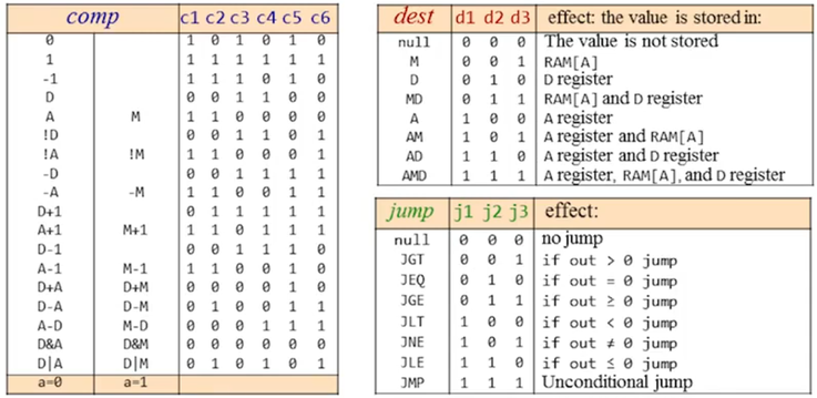
comp…everything the ALU supports - …
dest…registers and memory - …8 possible conditions for
jump…executeROM[A]
// set D regsiter to -1
D=-1

// set RAM[300] to value of D - 1
@300   // A=300
M=D-1  // R[300]=D-1

// if(D-1==0) jump …exe ROM[56]
@56       // A=56
D-1;JEQ   // if (D-1 == 0) goto 56
Hack Lang. Specification
Two ways to express the same semantics …binary code …symbolic language
Example @value …set A register
- …symbolic …
@21…non-negative decimal constant \(\leq32767(=2^{15}-1)\) - …binary …
0000000000010101…left most bit = opcode, followed by 15-bit number
Binary syntax of the C-Instruction…
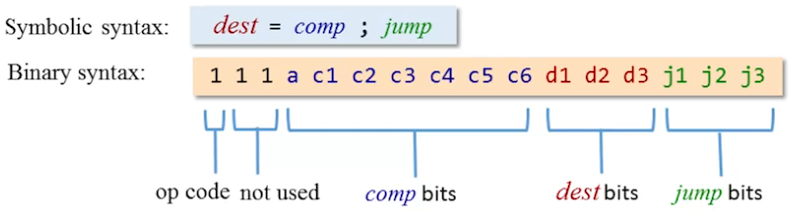
…center piece of the Hack machine language:
- Op code
1for a C-instruction (0for an A-instruction) - …followed by two unused bits
compbits …computation to do …bits send to the ALUdestbits …destination …jumpbits …conditions
Mapping from symbolic expressions to binary equivalent:
- Left side symbols …right side binary codes
- Note the
a-bit at the bottom of the table
Input/Output
Peripheral I/O devices… keyboard & screen (display) …used communicate with the user
- Low-level (hardware only) approach with bits… (high-level approach in part 2)
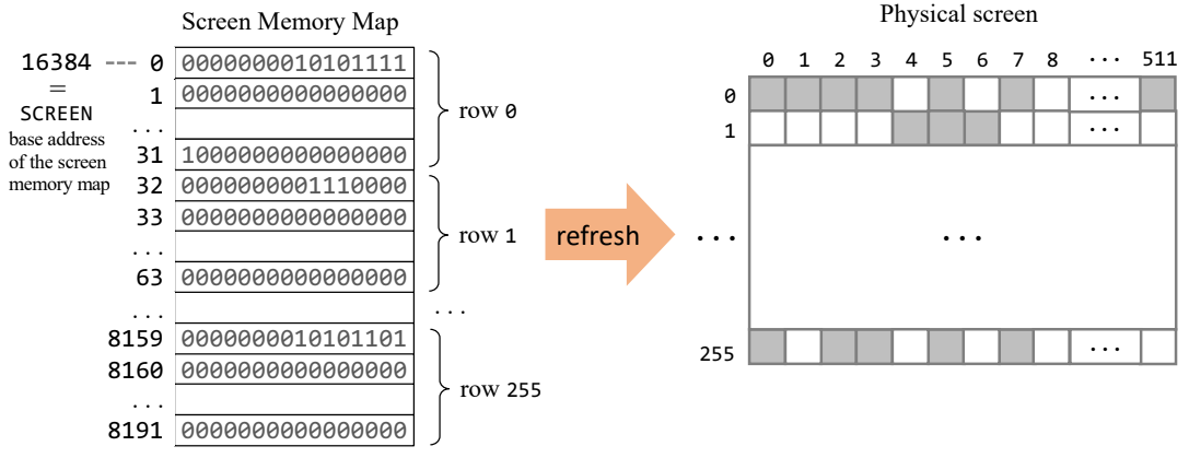
- …screen memory map → dedicated memory are to manage a display
- …physical display continuously refreshed (many times per second)
- …information to display available from the memory map
- …changes to screen = change memory map
Display:
- Display abstraction uses a matrix …intersections called pixels
- 512x256 (columns/rows) …pixel on
1…off0(black & white) - …memory map sequence of 16bit values (words)
- …total \(16*8192=131072 = 512*256\) …1 bit per pixel
- …in words 8k memory used to represent all pixels of the screen
- 512x256 (columns/rows) …pixel on
- Bitmaps …representation of \((row,col)\) pixel on physical screen
- Address
addra pixel…- …
addr=RAM[16384+32*row+col/16]absolute address in system memory - …base address of screen memory map at
RAM[16384] - …
addr=SCREEN[32*row+col/16]relative to screen bit map
- …
- …set the
(col%16)th bit ataddrto0or1
- Address
- Screen represented with a dedicated
Screenchip
Keyboard:
- Key press creates a scan code
- …dedicated scan code for each key …no key is
0 - …Hack computer supports subset of common keyboards
- …dedicated scan code for each key …no key is
- Keyboard memory register (16bit) at address
RAM[24576]
Hack Programming 1
Registers D data register …A address/data register M selected memory register M=RAM[A]
// D=10 …write a value into the data registger
@10      // write value 10 to register A
D=A      // store value from A register in register D

// D++ …increment value data register
D=D+1

// D=RAM[17] …read value from memory into data register
@17
D=M

// RAM[17]=D …write a value from data register into memory
@17
M=D

// RAM[5] = RAM[3] …move values in memory via data register
@3
D=M
@5
M=D
Example program to add two numbers:
@0
D=M   // D=RAM[0]

@1
D=D+M // D=D+RAM[1]

@2
M=D   // RAM[2]=D
Translate the program above with the Nand2Tetris assembler into binary code…
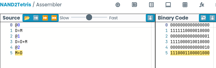
Load this binary code into the Nand2Tetris CPU emulator
- …populate the memory addresses
0and1with values - …run the program …watch content of register
AanD - …inspect the result in memory address
2
How to terminate a program… aka end in an infinite loop:
@6
0;JMP
Builtin symbols
- Virtual registers
R0..R15…convention to address first 16 memory addresses SCREEN&KBDfor display and keyboard memory map address
Hack Programming 2
Branch …goto …evaluation of boolean expressions
Example if R0 > 0 then R1 = 1 else R1 = 0
@R0
D=M        // D = RAM[0]

@8
D;JGT      // if R0 > 0 goto 7

@R1
M=0        // RAM[1] = 0
@10
0;JMP      // jump to end of program

@R1        // instruction 7
M=1        // R1 = 1

@10        // instruction 10
0;JMP      // endless loop
Symbols …any sequence of letters, _, ., $, : …does not begin with digit, but can contain digits
Reference symbols …labels
- …defined by the user …makes a program more readable
- …serve to label destinations for goto commands
- Pseudo command
(Xxx)…for label declaration- …interpreted by the assembler
- …defines labels
Xxxto reference the instruction memory location - …can only be defined once …can be used anywhere
- …its called pseudo commands since it does not generate machine code
- References
@LABELtranslates to@n- …where
nis the instruction number - …as defined by
(LABEL)
- …where
@R0
D=M

@POSITIVE   // using a label
D;JGT

@R1
M=0
@END
0;JMP

(POSITIVE)  // label decleration
@R1
M=1

(END)
@END
0;JMP
Variable symbols @Xxx …abstraction of a value
- …reference to a symbol without corresponding label declaration == variable
- …assembler assigns a memory address to represent
Xxx - …variable symbol translated to
@nwherenis the memory address - …allocated in RAM starting from address
16(0x0010) - …variables allocated to consecutive RAM locations
Flip.asm
// Flip value of RAM[0] and RAM[1]
@R1
D=M
@temp
M=D      // store R1

@R0
D=M
@R1
M=D      // R1 = R0

@temp
D=M
@R0
M=D      // write R0

(END)
@END
0;JMP
Iteration …iterative processing …example \(1 + 2 + … + n\)
- …recommended to design program with pseudo code …debug pseudo code
- …then translate pseudo code to assembly language
pseudo code
      n = R0
      i = 1
      sum = 0
LOOP:
      if i > n goto STOP
      sum = sum + i
      i = i + 1
      goto LOOP
STOP:
      R1 = sum
sumiton.asm
@R0
D=M
@n
M=D        // n = R0
@i
M=1        // i = 1
@sum
M=0        // sum = 0

(LOOP)
@i
D=M
@n
D=D-M
@STOP
D;JGT      // if i > n goto STOP

@sum
D=M
@i
D=D+M
@sum
M=D        // sum = sum + i
@i
M=M+1      // i = i + 1
@LOOP
0;JMP

(STOP)
@sum
D=M
@R1
M=D        // MEMORY[1] = sum

(END)
@END
0;JMP
Hack Programming 3
Pointers …variables that store memory addresses
- …semantics …set address register
Ato some memory address - …pointer logics …address memory with instruction like
A=M
@100
D=A
@arr
M=D     // arr = 100

@10
D=A
@n
M=D     // n = 10

@i
M=0     // i = 0

(LOOP)
@i
D=M
@n
D=D-M
@END
D;JEQ   // if (i==n) goto END

@arr
D=M
@i
A=D+M
M=-1    // MEMORY[arr+i] = -1

@i
M=M+1   // i = i + 1

@LOOP
0;JMP

(END)
@END
0;JMP
I/O pointer manipulation …predefined symbols …SCREEN address 16384 (0x4000)
Example using a screen device …draw rectangle in upper left corner
- …16 pixels wide …
RAM[0]pixels long - …manipulate the screen memory map
pseudo code
addr = SCREEN
n    = RAM[0]
i    = 0

LOOP:
    if i > n goto END
    RAM[addr] = -1      // 111111111111111
    addr = addr + 32    // next row (32 words in a row (32 * 16 = 512))
    i = i + 1
    goto LOOP
END:
    goto END
rectangle.asm
@R0
D=M
@n
M=D     // n = RAM[0]
@i
M=0     // i = 0
@SCREEN
D=A
@address
M=D     // address = 16384 (base address of the Hack screen)

(LOOP)
@i
D=M
@n
D=D-M
@END
D;JGT   // if i > n goto END

@address
A=M     // writing to memory using a pointer
M=-1    // RAM[address] = -1 (1111111111111111 for 16 pixels)

@i
M=M+1   // i = i + 1
@32
D=A
@address
M=D+M   // address = address + 32
@LOOP
0;JMP   // goto LOOP

(END)
@END
0;JMP
Handling keyboard (symbol KBD address 24576)
- Read address
KBDto check if a key is pressed- …no key pressed if
0…else scan-code - …for example
0000000001001011= scan-code 75 = character “k”
- …no key pressed if
Project 4
Algebraic program
- …multiply values in
RAM[0]andRAM[1]…store result inRAM[2] - …values
>= 0and result of multiplication<32768 - …multiplication by process of repeated addition for example \(3*4=3+3+3+3\)
pseudo code
RAM[2] = 0
n      = RAM[1]

if n = 0 goto END

LOOP:
    RAM[2] = RAM[2] + RAM[0]
    n = n - 1
    if n > 0 goto LOOP

END:
    goto END
mult.asm
@R2
M=0
@R1
D=M
@END
D;JEQ
@n
M=D

(LOOP)
@R0
D=M
@R2
M=D+M
@n
M=M-1
D=M
@LOOP
D;JGT

(END)
@END
0;JMP
Interactive program
- …listen to the
KBD - …on key press …blacken the screen
- …key release …clear screen
- …set speed to fast!
fill.asm
@color
M=0       // white by default

(LOOP)

  @SCREEN
  D=A
  @pixels
  M=D  // pixel address, goes from 16384 to 16384 + 8192 == 24576

  @KBD
  D=M
  @BLACK
  D;JGT     // if(keyboard > 0) goto BLACK

  @color
  M=0       // set to white
  @COLOR_SCREEN
  0;JMP     // jump to subroutine that colors the screen

  (BLACK)
    @color
    M=-1    // set to black (2's complement 111111111...)

  (COLOR_SCREEN)
    @color
    D=M
    @pixels
    A=M         // VERY IMPORTANT! indirect address
    M=D         // color M[pixels] with @color

    @pixels
    M=M+1
    D=M

    @24576
    D=D-A
    @COLOR_SCREEN
    D;JLT

@LOOP
0;JMP // infinite loop
Perspective
Hack machine language very simple…
- …simple on purpose to be achievable to learn quickly
- …typical machines have more advanced hardware/instructions
- Many machine languages allow to express operand and operator in a single instruction …Hack require an address- & compute-instruction
- Machine language designed for hardware and efficiency (not humans)
- …developers don’t write machine language …use of compilers
- …unless performance optimization
Unit 5
Computer ⇒ Machine that uses instructions to manipulate data
- Stored program concept (1930)
- …versatility …infinite array of tasks possible
- …fixed hardware (repertoire of instructions)
- …logic of programs not embedded in hardware
- …software just like data …many programs run on the same hardware
- …data & software stored in binary
- Computer architecture …basic loop: fetch & execute instructions
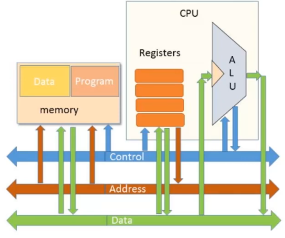
Computer ⇒ Set of chips connected by communication buses
- Information flow (wired by a communication bus)
- …control …which instruction to execute
- …address …where is the data instruction execute on
- …data …to operate on
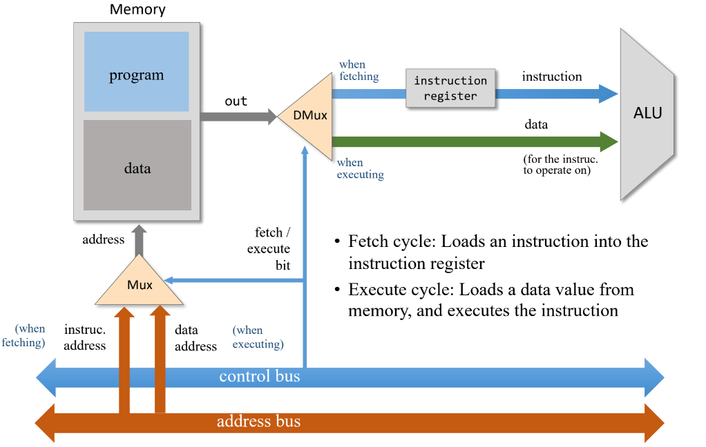
Fetch-Execute Cycle
CPU control unit …operation “fetch …decode …execute”
- Fetch instruction from program memory
- Program Counter (PC) …address of next instruction
ROM[PC]
- Program Counter (PC) …address of next instruction
- Decode instruction (“what to do”) …signal the hardware components
- …instruction bits specify which ALU operation to perform
- …on which operands (CPU registers/memory address)
- Execute …involves registers …data memory
Issue: Should memory output be interpreted as instruction or data?
- Possible solutions…
Multiplexor used to switch addressing between instruction & data memory
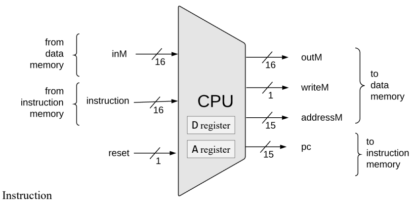
Central Processing Unit
CPU (Central Processing Unit)
- CPU Abstraction …execute current instruction …figure out which instruction to execute next
- Interfaces (to Hack architecture)
- …inputs: from memory (data & instruction) …reset bit
- …outputs: output data & address …write enable bit …program counter
Hack CPU implementation (components build in previous projects)
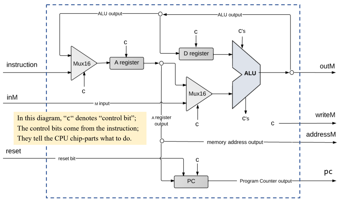
CPU instruction handling
- …opcode
0identifies an A-instruction- …decode instruction …op-code + 15 bit value
- …store value in A-register
- …output value
addressM
- …opcode
1identifies a C-instruction- …decode …ALU control bits …destination load bits …jump bits
- …route ALU output to A-register
- Note the opcode sets the control bit…
- …A-instruction …treated as value for A-register
- …C-instruction …prime A-register to get output from ALU
ALU operations:
- Multiplexor selects inputs between A-register or M-register
- 6 control bits from instruction
- Result of ALU calculation …simultaneously send to D-, A- & M-registers
- …destination bits select which registers are actually used
- …ALU control bits …negative & zero output flags
Program counter abstraction
PC=0…start/restart (reset bit)PC++…no jump (increment) …next instruction in memoryPC=A…goto …read next instruction address from A-register
The Hack Computer
Computer capable of running Hack machine language programs build from Hack chips
Hack CPU operations examples:
D=D-A- …read values from
DandAregisters - …compute in the ALU …write result to D-register
- …read values from
@17- …store value in A-register
- …emit value by
addressM
M=M-1- …read from
inM - …compute in the ALU
- …emit result to
outM…assertwriteMbit
- …read from
D=D-1;JEQ
Project 5
Memory architecture …aggregates three chips
- …
Screen&Keyboardchips builtin- …run the web hardware emulator full screen to see keyboard & display
- …note that the instruction memory is build with the
ROM32kchip
- Map the
addressinput onto the address inputs of the relevant chip-part- …single address space
0…24576(0x6000) - …addresses…
RAM16K→0…16383(0x0000…0x3fff)Screen(8k) →16384…24575(0x4000…0x5ffff)Keyboard→24576(0x6000)
- …single address space
Address boarders in binary…
- …bits
13&14significant to select memory region 00/01addresses RAM,10addresses the screen,11the keyboard
0x3fff       0011 1111 1111 1111
0x4000       0100 0000 0000 0000
0x5fff       0101 1111 1111 1111
0x6000       0110 0000 0000 0000
Memory chip implementation…
memory.hdl
CHIP Memory {
    IN in[16], load, address[15];
    OUT out[16];

    PARTS:
    // Addressing based on bits 13/14…
    //                                     00       01       10      11
    DMux4Way(in=load, sel=address[13..14], a=sRam0, b=sRam1, c=sScr, d=sKbd);
    // …either 00 or 01 selects RAM
    Or(a=sRam0, b=sRam1, out=sRam);

    // input to the selected chip
    RAM16K(in=in, load=sRam, address=address[0..13], out=ramOut);
    Screen(in=in, load=sScr, address=address[0..12], out=scrOut);

    // output from the selecd chip
    Keyboard(out=kbdOut);
    Mux4Way16(a=ramOut ,b=ramOut ,c=scrOut ,d=kbdOut ,sel=address[13..14] ,out=out );
}
CPU
- …use
ARegisterandDRegister
CPU.hdl
CHIP CPU {

    IN  inM[16],         // M value input  (M = contents of RAM[A])
        instruction[16], // Instruction for execution
        reset;           // Signals whether to re-start the current
                         // program (reset==1) or continue executing
                         // the current program (reset==0).

    OUT outM[16],        // M value output
        writeM,          // Write to M?
        addressM[15],    // Address in data memory (of M)
        pc[15];          // address of next instruction

    PARTS:

    // decode a c-instruction
    Mux16(a=false, b=instruction, sel=instruction[15],
          out[0]=cJGT,    out[1]=cJEQ ,  out[2]=cJLT ,
          out[3]=cDstM,   out[3]=writeM,
          out[4]=cDstD,   out[5]=cDstA,
          out[6]=cAluNo,  out[7]=cAluF,
          out[8]=cAluNy,  out[9]=cAluZy,
          out[10]=cAluNx, out[11]=cAluZx,
          out[12]=cAOrM,  // bits 13/14 unused
          out[15]=cType
          );

    ALU(x=xIn, y=yIn,
        zx=cAluZx, nx=cAluNx, zy=cAluZy, ny=cAluNy,
        f=cAluF, no=cAluNo,
        out=aluOut, out=outM,
        zr=aluZero , ng=aluNg);


    // Feed A-register from ALU or instruction memory
    Mux16(a=instruction, b=aluOut, sel=cType, out=aMuxOut);

    // Load register A
    Not(in=cType, out=notCType);
    Or(a=notCType, b=cDstA, out=loadA);
    ARegister(in=aMuxOut, load=loadA, out=aRegOut, out[0..14]=addressM);
    // Select a-register or memory ...feed ALU
    Mux16(a=aRegOut, b=inM, sel=cAOrM, out=yIn);

    // Select D-register ...feed ALU
    DRegister(in=aluOut, load=cDstD, out=xIn);

    // Jump logic
    Or(a=aluZero, b=aluNg, out=ltEq);
    Not(in=ltEq , out=posp);
    And(a=cJEQ, b=aluZero, out=JEQ);
    And(a=cJLT, b=aluNg,   out=JLT);
    And(a=cJGT, b=posp,    out=JGT);
    Or(a=JEQ, b=JLT,       out=JLE);
    Or(a=JLE, b=JGT,       out=jump);
    PC(in=aRegOut, load=jump, inc=true, reset=reset, out[0..14]=pc);
}
Part 2
From Nand to Tetris Part 2, 2018, Youtube
https://www.youtube.com/watch?v=KBTg0ju4rxM&list=PLrDd_kMiAuNmllp9vuPqCuttC1XL9VyVh
Footnotes
From Nand to Tetris in 12 steps, Shimon Schocken, Google Talks, 2011
https://www.youtube.com/watch?v=IlPj5Rg1y2w↩︎The Elements Of Computing Systems (2005), Internet Archive
https://archive.org/details/TheElementsOfComputingSystems_201408↩︎From NAND to Tetris, Tea Leaves, Youtube
https://www.youtube.com/watch?v=tRT1O6mLTZw&list=PLu6SHDdOToSdD4-c9nZX2Qu3ZXnNFocOH↩︎The Hack computer from nand2tetris on breadboards, Tomer Kronik, 2022
https://hackaday.io/project/185131-the-hack-computer-from-nand2tetris-on-breadboards/details↩︎Nand to Tetris projects 1-12
https://www.nand2tetris.org/course
https://github.com/nand2tetris/projects↩︎Hack Computer, Wikipedia
https://en.wikipedia.org/wiki/Hack_computer↩︎From Nand to Tetris Part 1, 2018, Youtube
https://www.youtube.com/watch?v=LqirVc5SlW0&list=PLrDd_kMiAuNmSb-CKWQqq9oBFN_KNMTaI↩︎From Nand to Tetris, Official Website
https://www.nand2tetris.org↩︎NAND2Tetris Hardware Simulator
https://nand2tetris.github.io/web-ide↩︎Lecture 2 Slides, GoogleDrive
https://drive.google.com/file/d/1ie9s3GjM2TrvL7PrEZJ00gEwezgNLOBm/view↩︎The Hack Chip Set, GoogleDrive
https://drive.google.com/file/d/1IsDnH0t7q_Im491LQ7_5_ajV0CokRbwR/view↩︎von Neumann architecture, Wikipedia
https://en.wikipedia.org/wiki/Von_Neumann_architecture↩︎Harvard architecture, Wikipedia
https://en.wikipedia.org/wiki/Harvard_architecture↩︎