Arduino Uno - Controlling a DC Motor
Even small DC motors can draw more current than the 40mA maximum provided by an Arduino UNO on a single GPIO pin. By using a Darlington Transistor it is possible to control a separate 9V battery power source for the motor able to provide much higher current.
The base activation voltage for a Darlington Transistor pair is the sum of 2 x 0.7V = 1.4V. With a 2kΩ resistor at the base of the transistor the current drawn from the connected Arduino used to control the motor will be limited to approximate 1.8mA.
(5V-1.4V)/2000Ω = 1.8mAThe TIP120 NPN (121/122) are rated for voltages of at least 60V and a current up to 5A. This Darlington transistor pair acts like one transistor with a current gain of the product of both individual transistors. The data sheet states a current gain up to 1000. This is more than sufficient to drive a small DC motor.
Components
List of required components:
| Pcs. | Name | Description |
|---|---|---|
| 1 | UNO | Arduino UNO, digital pins D#2 and D#9 |
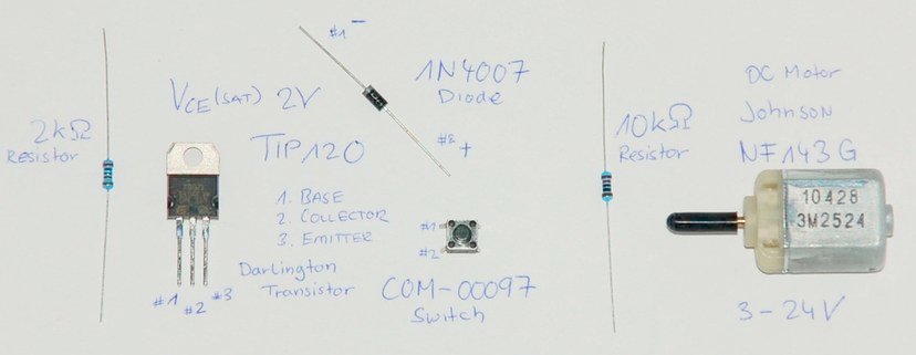
| 1 | M1 | DC motor Johnson NF143G-10428 |
| 1 | TIP | TIP120 Darlington Transistor #1 base, #2 collector, #3 emitter |
| 1 | D1 | 1N4001 Diode collector #1 (-) and anode #2 (+) |
| 1 | R1 | Resistor 10kΩ |
| 1 | R2 | Resistor 2kΩ |
| 1 | B1 | COM-00097 push button (single pole, single throw) |
Setup
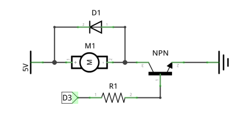
List of connections:
- Button B1 terminal #1 to 5V
- Button B1 terminal #2 to the R1 resistor terminal #1
- Button B1 terminal #2 to pin D#2 on the Arduino UNO
- Resistor R1 terminal #2 to ground GND
- Transistor TIP base terminal #1 to R2 resistor terminal #2
- Resistor R2 terminal #2 to pin D#9 on the Arduino UNO
- Transistor TIP collector terminal #2 to diode D1 collector (negative) terminal #1
- Transistor TIP emitter terminal #3 to ground GND
- Diode D1 anode (positive) terminal #2 to 9V
- Motor M1 terminal #1 to diode D1 anode #2
- Motor M1 terminal #2 to diode D1 collector #1
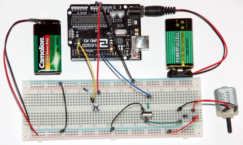
Connect the 9V battery (+/-) to the bottom breadboard power supply line, and connect 5V and GND pins from the Arduino UNO to the top breadboard power supply line. Connect ground of both breadboard supply lines.
Code
#define BUTTON 2
#define MOTOR 9

void setup() {
  pinMode(BUTTON,INPUT);
  pinMode(MOTOR,OUTPUT);
}

void loop() {
  if(digitalRead(BUTTON) == HIGH) {
    analogWrite(MOTOR,255);
    delay(200);
  }
  delay(1);
}
Measurement
| Voltage Drop | |
|---|---|
| R2 resistor | 3.02V |
| TIP collector-base | 1.34V |
| TIP collector-emitter | 0.64V |
| M1 motor | 7.81V |
| Current | |
|---|---|
| TIP base | 1.5mA |
| TIP collector | 15.02mA |
If the motor shaft is blocked (can not continue to rotate) the stall current peaks at 105.5mA at the TIP collector.