Arduino Uno Analog I/O with PWM
Embedded
Electronics
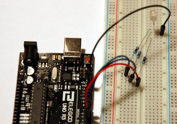
The RGB LED has four leads, one for each color (positive), and a common ground (negative). Each LED color lead requires a protection resistor R[1,2,3] (e.g. 220Ω).
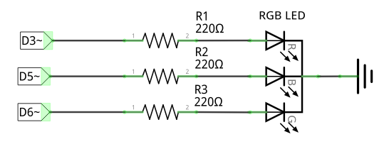
Connections
- Red lead → Arduino D3 (digital output, with PWM)
- Blue lead → Arduino D5 (digital output, with PWM)
- Green lead → Arduino D6 (digital output, with PWM)
- Common ground → Arduino GND (0V)
Implementation…
- An
rgbColor()function with arguments for each RGB color. It sends output to D[3,5,6] with analogWrite() - Call this function from the main
loop()to mix red, green, blue, yellow, purple, and aquamarine colors. - Write for-loops to iterate over all possible RGB colors.
/*

RGB (Red, Green, Blue) LEDs are able to mix any color
by controlling the brightness of three color channels:

- Each color channel can have a value between 0 and 255
- 256^3 combinations of RGB values are allowed

Control the brightness of an RGB LED with an analogue signal
using output pins supporting Pulse-Width Modulation.

*/

int msec = 1000; // 1 second

//
// Use one pin supporting PWN for each color
//
int rPin = 3; // red
int gPin = 6; // green
int bPin = 5; // blue

//
// Configure the RGB pins as output
//
void setup() {
  pinMode(rPin,OUTPUT);
  pinMode(bPin,OUTPUT);
  pinMode(gPin,OUTPUT);
}

//
// Set the output pins to a given color triplet
//
void rgbColor(int r, int g, int b) {
  analogWrite(rPin,r);
  analogWrite(gPin,g);
  analogWrite(bPin,b);
}

void loop() {
  //
  // Display different colors
  //
  rgbColor(255,0,0); // red
  delay(msec);
  rgbColor(0,255,0); // green
  delay(msec);
  rgbColor(0,0,255); // blue
  delay(msec);
  rgbColor(255,255,0); // yellow
  delay(msec);
  rgbColor(80,0,80); // purple
  delay(msec);
  rgbColor(0,255,255); // aqua
  delay(msec);

  for(int r = 0; r <= 255; r++) {
    for(int g = 0; g <= 255; g++) {
      for(int b = 0; b <= 255; b++) {
        rgbColor(r,g,b);
      }
    }
  }

}