Breadboard Transistor On-Off Switch
Electronics
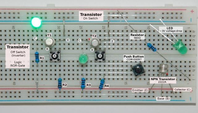
List or required components:
| Pcs. | Description |
|---|---|
| 2 | NPN transistor (e.g PN2222A) |
| 2 | LED |
| 4 | Resistor (e.g. 560Ω) |
| 2 | Push Button (e.g. COM-00097) |
| 1 | Breadboard including wires |
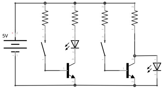
The base-emitter voltage of both transistors is controlled by push buttons. The on switch in the middle lights the LED if the button is pressed (enabling the A input):
Truth table (logic level “1” HIGH, and “0” LOW)
| A | Q |
|---|---|
| 0 | 0 |
| 1 | 1 |
The left circuit switches the LED off if the button is pressed. This is called an inverter, an represents the function of a logic NOT gate:
| A | Q |
|---|---|
| 0 | 1 |
| 1 | 0 |
The output Q from a NOT gate only return HIGH if the input is a logic level LOW.