Breadboard Flip-Flops & Latches
Electronics
Flip-flops are bi-stable (two state) devices:
- Most basic type of 1-bit memory.
- The internal state is “remembered” until changed by an input pulse, or until the power is removed.
- Different types of flip-flops are build from combinations of logic gates.
- Also called bi-stable Latch.
SR/RS Type
SR (Set-Reset) flip-flop is one of the simplest sequential circuits:
- Two inputs Set (S) and Reset (R), and two outputs (Q, and negated Q).
- Output set in one of two states, and will remain latched indefinitely.
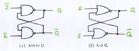
Build from to NAND/NOR gates:
- The output of each gate is connected to an input of the other gate (feedback loop, cross-coupling)
- Low-activated SR Flip-Flop (“NOT” indicated by the bar above the letter)
- High-activated RS Latch
List of required components to build an RS Latch with a breadboard:
| Pcs. | Description |
|---|---|
| 1 | 74xx02 Quad 2 input NOR Gates |
| 2 | COM-00097 Switch |
| 2 | 560Ω Resistor |
| 2 | LED (green) |
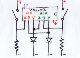
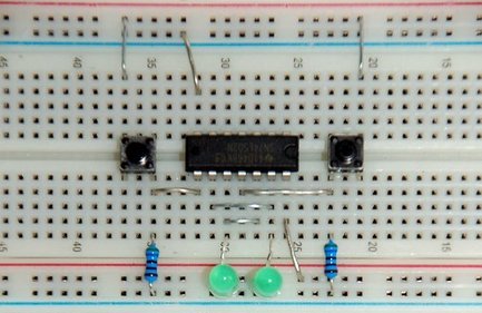
Truth table for an RS Latch:
| S | R | Q | !Q | Comment |
|---|---|---|---|---|
| 0 | 1 | 1 | 0 | (a) Q is set to 1 by 1 on S |
| 0 | 0 | 1 | 0 | (b) no change after set |
| 1 | 0 | 0 | 1 | (c) Q is rest to 0 by 1 on R |
| 0 | 0 | 0 | 1 | (d) no change after reset |
| 1 | 1 | 0 | 0 | (e) not allowed (both outputs at zero) |
| 0 | 0 | ? | ? | (f) if both inputs change from 11 to 00, output is indeterminate |
References
- Datasheet SN74LS02N, Texas Instruments
- SR Latch, Ben Eater
- Sequential Logic Circuits
D Latch
Circuit symbols for D type devices:
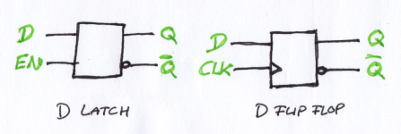
A D latch is like an RS latch with only one input:
- Overcomes the drawbacks of the SR/RS type devices (e,f).
- Does not respond to a data input D unless the enable input EN is 1.
- While the circuit is enabled the D input sets the outputs Q, and de-activating the D input resets the circuit.
- If the circuit is not enabled then the Q outputs stay latched, unresponsive to the state of the D input.
List of required components to build a D Latch:
| Pcs. | Description |
|---|---|
| 1 | 74xx02 Quad 2 input NOR Gates |
| 1 | 74xx08 Quad 2 input AND Gates |
| 2 | COM-00097 Switch |
| 3 | 560Ω Resistor |
| 3 | LED (green/red) |
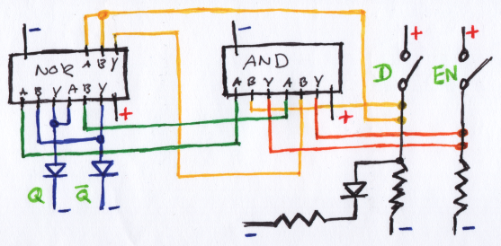
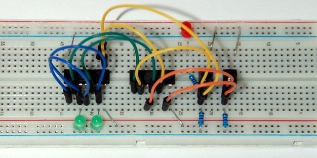
Truth table:
| EN | D | Q | !Q |
|---|---|---|---|
| 0 | 0 | latch | latch |
| 0 | 1 | latch | latch |
| 1 | 0 | 0 | 1 |
| 1 | 1 | 1 | 0 |
References…
- Datasheet SN74LS08N, Texas Instruments
- D Latch, Ben Eater
- Gated D Latch, Wikipedia
D Flip-Flop
List of additional components for the clock input CLK:
| Pcs. | Description |
|---|---|
| 1 | 1µf ceramic capacitor |
| 1 | 1kΩ resistor |
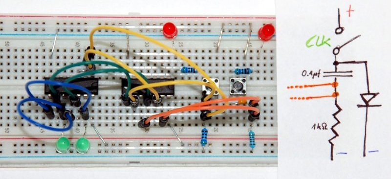
References …D Flip Flop, Ben Eater