Raspberry Pi Pico - MicroPython Get Started
The book Get Started with MicroPython on Raspberry Pi Pico [01] is a great introduction for everyone without any experience in embedded micro-controllers nor the Python programming language. Alternatively for people with a little bit more background the Raspberry Pi Pico Python SDK documentation [02] may be more suitable. The following are my notes from reading the Get Stated… book myself. You’ll find plenty of references to related material in the following text.
Both documents describe the process of installing the pre-build MicroPython firmware on the Raspberry Pi Pico. This is a required prerequisite since the Pico is not sold with MicroPython installed. Furthermore they include a recommendation to use the Thonny IDE which includes a very handy console to interact with MicroPython REPL on the Pico. For this purpose I have followed their advice and can agree that it is an easy editor to use for beginners.
There is a lot of other great introduction material available covering first steps with the Pico including many videos on Youtube with detailed demonstrations. I leave it to you to explore all the alternatives.
Input/Output - GPIO
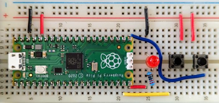
My first hello world example used the following breadboard setup with an LED, a resistor (around 250 Ohm) and a button. The first chapters of Get Started with MicroPython on Raspberry Pi Pico [01] describe at length how to get here. It is mainly the steps to get familiar with the process of working with the Pico for development.

The code below should look mostly familiar to anyone with some basic understanding of Python. The Raspberry Pi Pico hardware is exposed through the standard MicroPython machine module:
import machine
import utime

# GP15 ...physical pin 20
led_external = machine.Pin(15, machine.Pin.OUT)
# GP14 ...physical pin 19
button = machine.Pin(14, machine.Pin.IN, machine.Pin.PULL_DOWN)

while True:
    if button.value() == 1:
        led_external.value(1)
        utime.sleep(1)
    led_external.value(0)
The machine.Pin class controls the GPIO pins to drive an output voltage or read an input voltage:
- Argument one is the number of the pin to use. As you can see in the Pico Pinout the general purpose
GP*numbers do not align with numbering for the physical pins. Therefore GP15 corresponds to physical pin 20. - The second argument specifies the pin mode. The most commonly used are
Pin.INandPin.OUTto configure for input or output. - The optional third argument specifies if the pin has a pull resistor attached. For the button the argument is set to
machine.Pin.PULL_DOWN, meaning the pin has to be pulled high when the push-button switch is pressed. In order to do that the button needs to be wired to 3V.
Dual Core - Threads
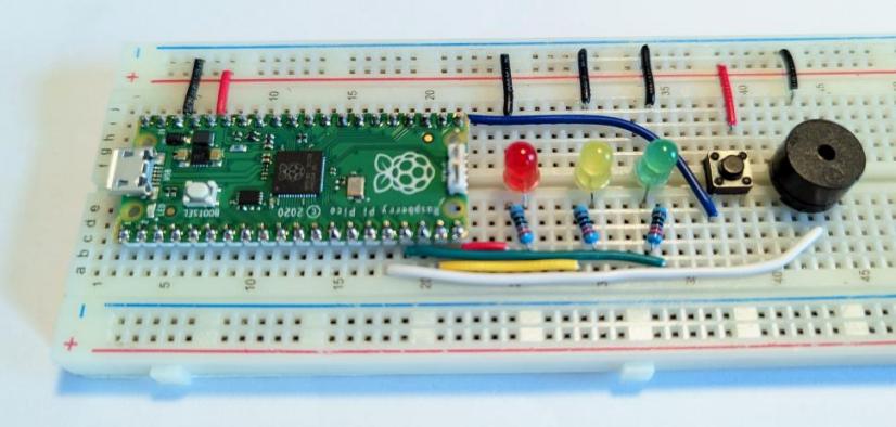
Chapter five in Get Started with MicroPython on Raspberry Pi Pico [01] introduces the _thread module with a traffic light example. Pressing the button waits until the next time the light is red to use a buzzer as signal to pedestrians. Multithreading is the ability of a CPU (central processing unit) to provide multiple threads of execution concurrently. Threads share the resources with multiple cores on a CPU including…
…resources such as memory. In particular, the threads of a process share its executable code and the values of its dynamically allocated variables and non-thread-local global variables… [03]
The Raspberry Pi Pico is built around the RP2040 micro-controller which includes a dual core ARM Cortex-M0+ CPU described in technical detail in the RP2040 Datasheet [05].

A thread is used in order to not interrupt the traffic light while waiting for a button press. According to the Raspberry Pi Pico Python SDK [02] section 3.5 only one (additional) thread can be started at any one time. Basically both processing cores on the micro-controller can run Python code concurrently. global variables are used to share data between threads.
import machine
import utime
import _thread

led_red = machine.Pin(15, machine.Pin.OUT) led_yellow = machine.Pin(14,
machine.Pin.OUT) led_green = machine.Pin(13, machine.Pin.OUT) button =
machine.Pin(16, machine.Pin.IN, machine.Pin.PULL_DOWN) buzzer = machine.Pin(12,
machine.Pin.OUT)

global button_pressed
button_pressed = False

def button_reader_thread():
    global button_pressed
    while True:
        if button.value() == 1:
            button_pressed = True
        utime.sleep(0.1)
_thread.start_new_thread(button_reader_thread, ())

while True:
    if button_pressed == True:
        led_red.value(1)
        for i in range(10):
            buzzer.value(1)
            utime.sleep(0.2)
            buzzer.value(0)
            utime.sleep(0.2)
        global button_pressed
        button_pressed = False
    led_red.value(1)
    utime.sleep(5)
    led_yellow.value(1)
    utime.sleep(1)
    led_red.value(0)
    led_yellow.value(0)
    led_green.value(1)
    utime.sleep(5)
    led_green.value(0)
    led_yellow.value(1)
    utime.sleep(3)
    led_yellow.value(0)
    led_red.value(1)
The MicroPython _thread module implements a subset of the corresponding CPython module. Specifically start_new_thread() which expects a function name as first argument. This named function will be executed in parallel by the second core.
Interrupt Requests - IRQs
The next chapter (six) in Get Started with MicroPython on Raspberry Pi Pico [01] exemplifies IRQs (interrupt requests) using the machine.Pin.irq() method by building a simple reaction game for two players. Reaction time is measured for player button presses when the LED lights off, after a random amount of time.

Following the explanation of an interrupt in Wikipedia [04]:
An interrupt is a request for the processor to interrupt currently executing code (when permitted), so that the event can be processed in a timely manner. If the request is accepted, the processor will suspend its current activities, save its state, and execute a function called an interrupt handler to deal with the event. This interruption is often temporary, allowing the software to resume[a] normal activities after the interrupt handler finishes, although the interrupt could instead indicate a fatal error.
The button_handler() function is defined to act as interrupt handle executed when a button is pressed. For this purpose both button pins set an interrupt handler to be called when the trigger source of the pin is active.
trigger=machine.Pin.IRQ_RISINGconfigures the event which can generate an interrupt, in this case on rising edge. Which is the moment when the pins value rises from low (thanks to the pull-down resistor) to high 3V.handler=specifies the callback function (aka interrupt handler) to execute when the interrupt event occurs.
import machine
import utime
import urandom

pressed = False
fastest_button = None

led = machine.Pin(15, machine.Pin.OUT)
left_button = machine.Pin(14, machine.Pin.IN, machine.Pin.PULL_DOWN)
right_button = machine.Pin(16, machine.Pin.IN, machine.Pin.PULL_DOWN)

# callback function for the interrupt
def button_handler(pin):
    global pressed
    if not pressed:
        pressed = True
        global fastest_button
        fastest_button = pin

# set up the interrupts
left_button.irq(trigger=machine.Pin.IRQ_RISING, handler=button_handler)
right_button.irq(trigger=machine.Pin.IRQ_RISING, handler=button_handler)

led.on()
# wait for a random amount of time between 5 and 10 seconds
utime.sleep(urandom.uniform(5, 10))
led.off()

while fastest_button is None:
    utime.sleep(1)

if fastest_button is left_button:
    print("Left player wins...")
elif fastest_button is right_button:
    print("Right player wins...")
Analog Input/Output - ADC & PWD
An analog signal is any continuous signal representing some quantity. Compared to a binary digital signal with 0V or 3.3V, analog signal voltage varies in between the 0V and 3.3V. Typically analog signals represent measurements of light, sound, pressure, temperature or humidity.
Analog signal processing requires an ADC (analog-to-digital converter). The RP2040 has an internal ADC (section 3.3 [01] & section 4.9 [05]) that measures some analogue signal and encodes it as a digital number. An ADC has two key features…
- …resolution measured in digital bits. The RP2040 provides 12 bits as resolution with values from 0 to 4095. MicroPython transformed this to a 16-bit number ranging from 0 to 65,535 to stay conform to other micro-controllers.
- …the number of channels, analogue signals it can accept and convert. RP2040 provides three ADC channels brought out to the GPIO pins, a fourth to read the input voltage to the Pico and a fifth connected to an internal temperature sensor.
The RP2040 datasheet [05] describes the internal temperature sensor in section 4.9.5 in detail. The description includes a formula to approximate the temperature from the ADC voltage read by the sensor. Note that the reading is not necessarily accurate since it depends on the reference voltage of 3.3V. 1% change in reference voltage deviates the temperature by 4℃.
MicroPython includes the machine.ADC class which provides an interface to analog-to-digital converters. The class constructor requires the pin object to use as input channel. ADC.read_u16() return an integer in the range 0-65535 that represents the raw reading taken by the ADC. Convert the reading into a voltage by dividing the maximum voltage 3.3V by the maximum value the ADC can read multiplied by the ADC reading.
import machine
import utime

sensor_temp = machine.ADC(4) # internal temperature sensor
conversion_factor = 3.3/(65535)

while True:
    # caluculate the voltage from the ADC reading
    reading = sensor_temp.read_u16() * conversion_factor
    # forumla to approximate temperature from the ADC voltage
    temperature = 27 - (reading - 0.706)/0.001721
    print(temperature)
    utime.sleep(2)
Analog output ca be generated with PWM (pulse-width modulation) [06].
Turning a digital output on and off is known as a pulse and by altering how quickly the pin turns on and off you can change, or modulate, the width of these pulses – hence ‘pulse-width modulation’. [01]
In other words, a digital signal provides a smoothly varying average voltage. This is achieved with positive pulses of some controlled width, at regular intervals (section 4.5 [05]).

The machine.PWM class provides pulse width modulation output in MicroPython. The constructor expects the output pin as argument. The pico supports to drive all GPIO pins with PWM. PWM.freq() sets the frequency for the PWM output in Hz.PWM.duty_u16() accepts a range 0 to 65535.
import machine
import utime

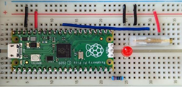
potentiometer = machine.ADC(26)
led = machine.PWM(machine.Pin(15))
led.freq(1000)

while True:
    led.duty_u16(potentiometer.read_u16())
    utime.sleep(1)
Note that a more accurate way to generate an analog output signal is to use a DAC (digital-to-analogue converter), however the RP2040 (as most micro-controllers) does not include a DAC.
Non-volatile Storage & Headless Operation
Raspberry Pi Pico pairs the RP2040 microcontroller with 2MB on-board flash memory (connected via QSPI). It can be used as non-volatile storage, an alternative to dedicated peripheral storage components. Chapter 8 illustrates writing to the on-board storage by logging the temperature from the on-board sensor.
import machine
import utime

sensor_temp = machine.ADC(machine.ADC.CORE_TEMP)

conversion_factor = 3.3/65535
file = open("temps.txt", "w")

while True:
    reading = sensor_temp.read_u16() * conversion_factor
    temperature = 27 - (reading - 0.706)/0.001721
    file.write(str(temperature) + "\n")
    file.flush()
    utime.sleep(10)
MicroPython uses the available flash storage and will set up a file-system upon first boot. The internal file-system section in the MicroPython documentation describes reading and writing files.
Chapter 8 additionally introduces the capability of the Pico to run without a connected computer in headless operation (being powered by a battery for example). MicroPython executes a main.py file automatically on power-on or reset if available. (Note that pressing ctrl-d in the console will soft-reset the Pico, to for example start into main.py)
References
Following a list of reading recommendations…
[01] Get Started with MicroPython on Raspberry Pi Pico, Raspberry Pi Press
https://hackspace.raspberrypi.com/books/micropython-pico
[02] Raspberry Pi Pico Python SDK, Raspberry Pi
https://datasheets.raspberrypi.com/pico/raspberry-pi-pico-python-sdk.pdf
[03] Computers - Thread, Wikipedia
https://en.wikipedia.org/wiki/Thread_(computing)
[04] Computers - Interrupt, Wikipedia
https://en.wikipedia.org/wiki/Interrupt
[05] RP2040 Micro-Controller Datasheet, Raspberry Pi
https://datasheets.raspberrypi.com/rp2040/rp2040-datasheet.pdf
[06] Pulse-width Modulation (PWM), Wikipedia
https://en.wikipedia.org/wiki/Pulse-width_modulation