Raspberry Pi Pico - Scoppy Oscilloscope
The Android Scoppy App [01] is an oscilloscope and logic analyzer interfacing with a circuit using a Raspberry Pi Pico. An oscilloscope or just scope is a test instrument to analyze and debug electrical circuits. Basically it helps to understand the relationship between voltage and time by visualizing it on a 2D graph with x-axis time and y-axis voltage.
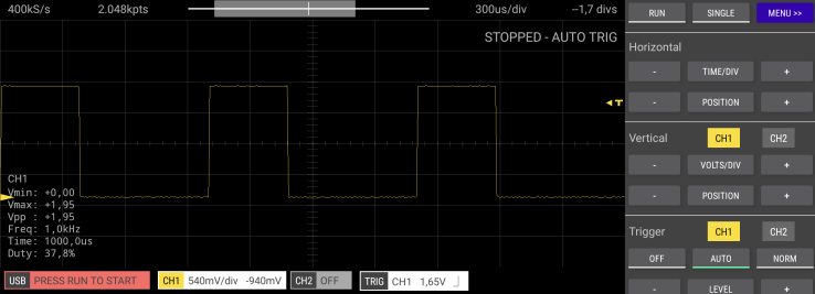
The graph visualizes frequency and amplitude of an repetitive oscillating signal, a so called waveform. The screenshot above depicts a square wave, or periodic waveform that alternates at a steady frequency between fixed minimum and maximum values.
Prerequisites
The Scoppy project page [00] includes all information to get started. Follow the installation instruction…
# ...download the firmware
wget https://fhdm-dev.github.io/downloads/scoppy-pico-v14.uf2- Download the firmware from the Scoppy project page
- Flash the firmware to the Raspberry Pi Pico…
- Hold BOOTSEL…
- …connect the Pico via USB…
- …release BOOTSEL after at least 3 seconds
- …copy the firmware to the device.
- Install Scoopy Android App [01] on a smart device.
- Connect the smart device to the Pico using an OTG adapter cable.
Test the basic functionality using the 1kHz square wave (duty cycle of 50%) signal provided by the Pico itself. Connect GPIO22 to the ADC on GPIO26 and press run.
Oscilloscope Example
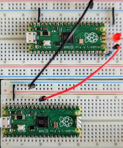
Instead of using a test signal from the Pico running Scoopy, well capture a very simple PWM (pulse width modulation) signal from another Pico. On the image below you can see the breadboard setup…
- …the Pico on the bottom runs Scoopy.
- …the pico on the top runs a very simple code to generate a PWM signal.
GPIO26 is connected with the signal source on the top Pico (note that the input signal needs to be captured before the LED).
The following Micropython code generates a 1kHz signal with varying duty cycle. The duty cycle represents the ratio of how long a signal is positive 3.3V vs negative 0V for each period (time each repeating waveform takes).
import machine
import utime

led = machine.PWM(machine.Pin(15))
led.freq(1000)

while True:
    led.duty_u16(5000)
    utime.sleep(3)
    led.duty_u16(15000)
    utime.sleep(3)
    led.duty_u16(25000)
    utime.sleep(3)
    led.duty_u16(35000)
    utime.sleep(3)
    led.duty_u16(45000)
    utime.sleep(3)
    led.duty_u16(55000)
    utime.sleep(3)
PWM uses a digital signal to provide a smoothly varying average voltage with a given frequency:
- Set a frequency of 1000Hz (1kHz) with the
machine.PWM.freq()method. - The duty cycle is represented with a range from 0 to 65535 and ist set with the
machine.PWM.duty_u16method.
Logic Analyzer Example
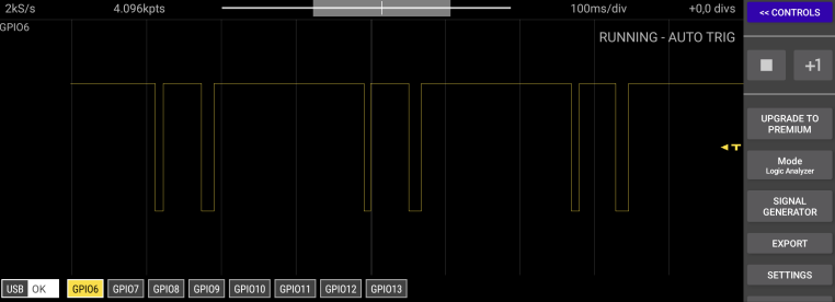
The second mode of Scoopy operates as logic analyzer to capture signal from digital circuits. It measures and analyzes signals differently than an oscilloscope and detects logic threshold levels. The screenshot below illustrates that the logic analyzer is only concerned with logic states of a signal over time.
Typically it is use to trace and correlate many digital signals simultaneously. Mostly to detect and analyze timing violations and transients on communication buses. Below is the breadboard setup to trace a single input channel. The image shows the use of small test hooks which are used to grep on to a wire or pin.
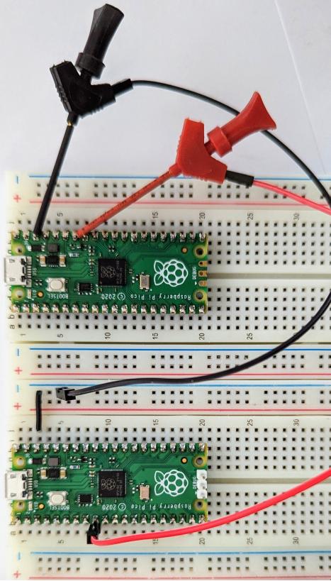
The bottom Pico runs Scoopy, and the yop Pic generate a simple digital signal in a endless loop.
import machine
import utime

signal = machine.Pin(26, machine.Pin.OUT, machine.PIN.PULL_DOWN)

while True:
    signal.on()
    utime.sleep_ms(50)
    signal.off()
    utime.sleep_ms(20)
    signal.on()
    utime.sleep_ms(180)
    signal.off()
    utime.sleep_ms(10)
Conclusion
In the free version of Scoopy, both the oscilloscope and logic analyzer support a single channel. However, a very small in-app purchase extends the functionality to…
- …2 channel oscilloscope
- …8 channel logic analyzer
Scoppy supports not only the voltage range 0V to 3.3V of the Pico. Use of a front-end circuit enables different voltage ranges as well as protection against over-voltage and under-voltage. The FHDM store [02] provides a front-end with more advanced features. Scoopy provides a very affordable access to an oscilloscope and logic analyzer. The product page for the FSCOPE-500K describes the capabilities when using the front-end PCB.
References
[00] Scoppy - Oscilloscope and Logic Analyzer
https://oscilloscope.fhdm.xyz
[01] Scoppy - Oscilloscope, Google Play Store
https://play.google.com/store/apps/details?id=xyz.fhdm.scoppy
[02] FHDM Store
https://store.fhdm.xyz