
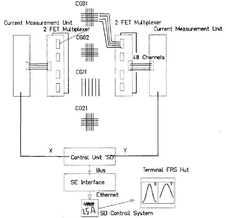
The CGs are used in the FRS to measure x and often also y position in the focal planes. There are:
| focal plane | simple name | nomenclature | type |
|---|---|---|---|
| S0 | CG01, CG02 | TS1DG5, TS2DG2 | small +/-38mm, X+Y |
| S1 | CG11 | TS3D2H | large +/-92mm, X |
| S2 | CG21 | TS3DG7 | small +/-38mm, X+Y |
| S3 | CG31 | TS4DG3H | large +/-92mm, X |
| S5 | CG51 | TS5DG1 | small +/-38mm, X+Y |
| S6 | CG61, CG62 | TE5DGCG, TE5DGDG | small +/-38mm, X+Y |
| S7 | CG71 | TS7DG1 | dismounted |
| S8 | CG81,CG82 | TH4DG4G, TH4DG5G | small, other type |
The CGs collect secondary electrons produced in a window or foil
just in front of the detector wires or in a gas volume surrounding
the wires.
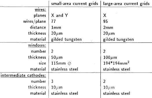
Some CGs have wires for X and Y direction others only for X. Wire
spacing is 1 mm.
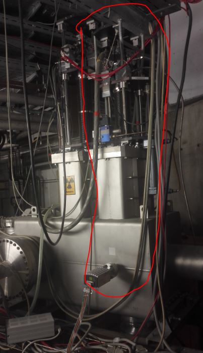
Photograph of CG61:
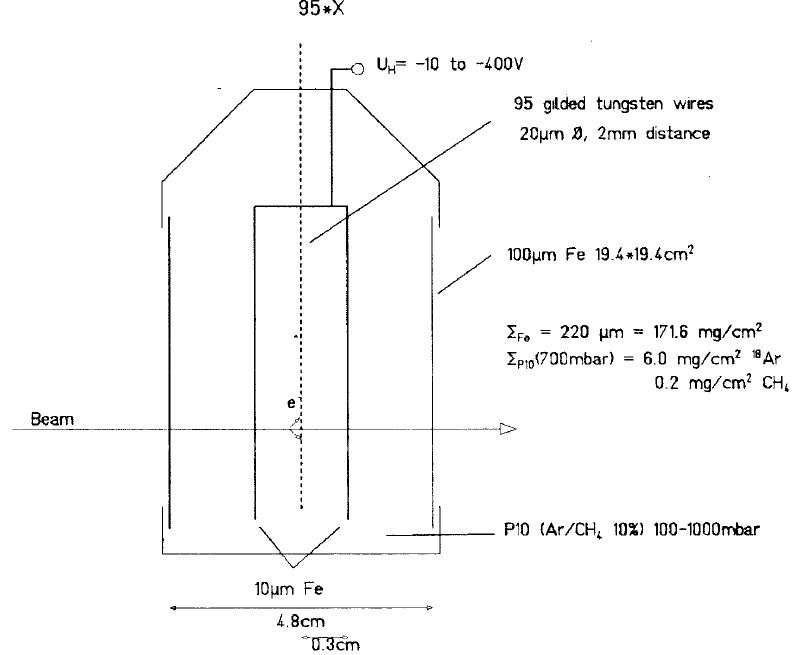
Left: sketch of type small size CG, right: type large size CG:
(figures from [2])
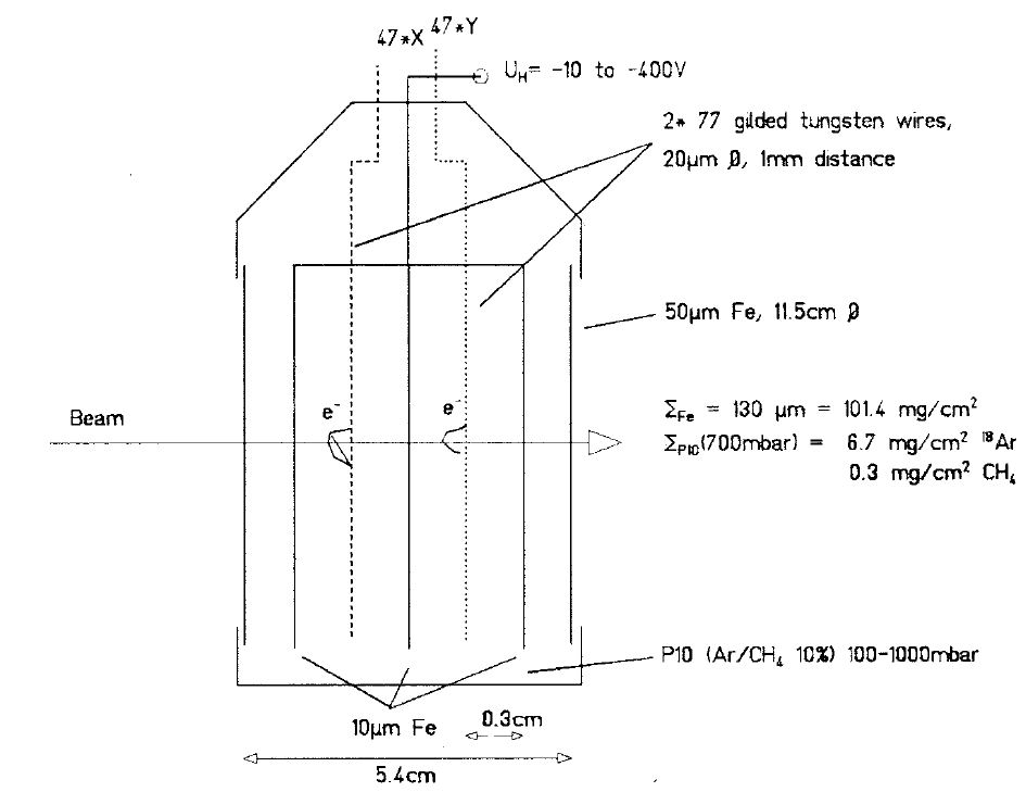
As only low energy electrons (max. few eV) have to be collected a
bias of about -10V on the cathode is enough to collect all.
To be safe also for for fast extraction with space charge
typically -90V are applied. Set values from CAEN HV crate.
Some CGs were tested up to -500V. However, this brings no gain in
signal height, but is dangerous (sparking).
As used in present the detectors are not foressen for
amplification even with gas filling. The gas only increases the
volume from where secondary electrons can be emitted. Otherwise
only a very thin layer of a solid would contribute.
The original design was for real gas amplification and up to -400V
on the cathode plane. But then also gas at much lower pressure
must be used.
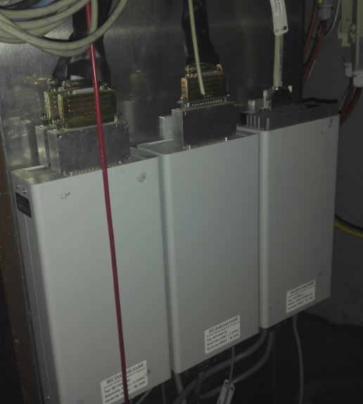
Left amplifiers (new type not used for FRS), right old type at S2:
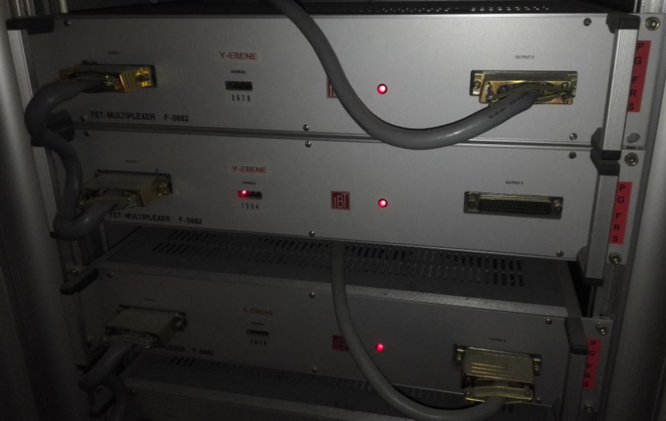
Multiplexer at S2:
To save readout channels for |x|>10mm always 2 wires are
combined to one channel, only for |x|<10mm the full resolution
of dx = 1 mm is used.
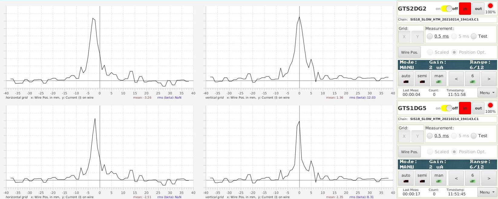
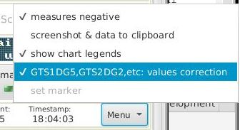
However, the old front-end computer already sorts them wrongly in the
transition region and creates artefact peaks around
x=10mm. to correct this bug there is a software option in the [Menu] button.
The menue also includes an option to export data to an ascii
list and a screenshot, which are copied to clipboard
(http://clipboard.acc.gsi.de/app-profilegrid/).
A full test without beam is not possible because detectors are inside the vacuum chamber.
But the amplifiers and readout can be tested.
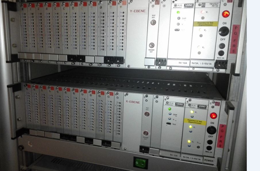
For this a pulser is integrated into the two CG controllers located in the
electronics room of FRS Messhütte.
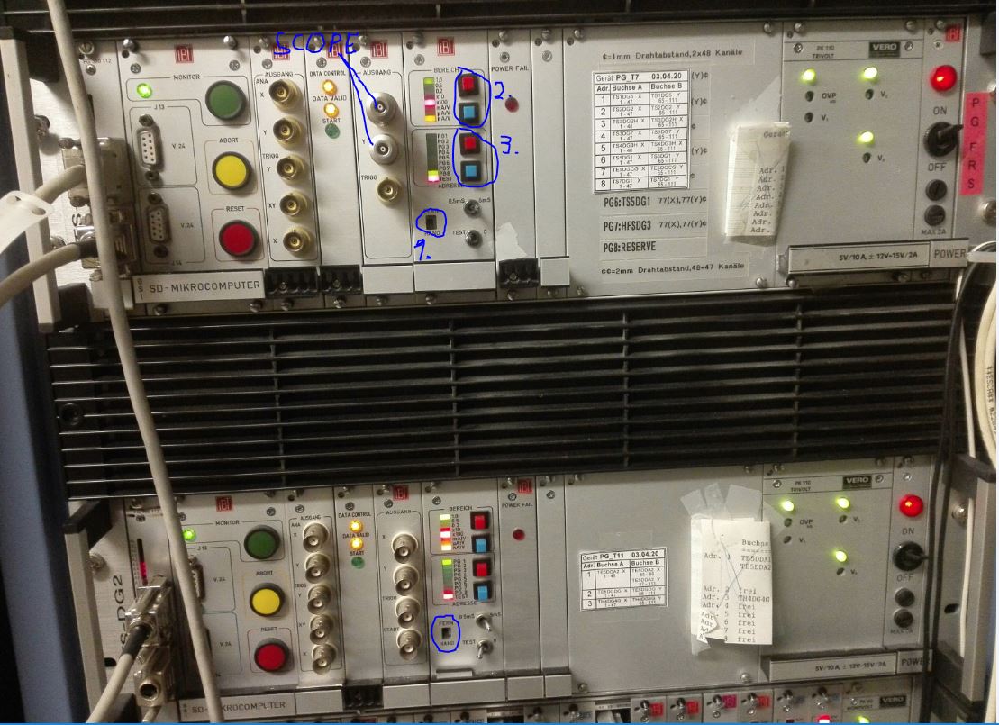
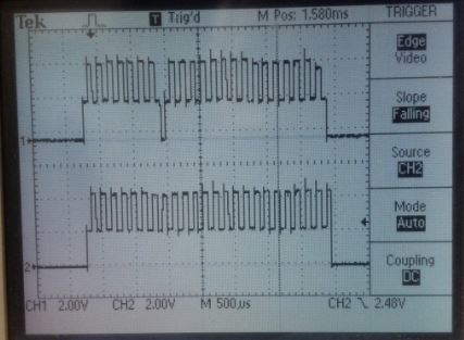
Connect oscilloscope to BNC connectors for X or Y direction. The sequential
readout should produce a regular pattern in time. Missing peaks
indicate a bad amplifier channel. Example: Picture on
oscilloscope, 48 channels with different resistors for alternating
height. Top x direction, below y direction, one bad channel (#16)
in x direction.
Results of a pulser test for all CGs done in Dec 2019
(pdf-file).
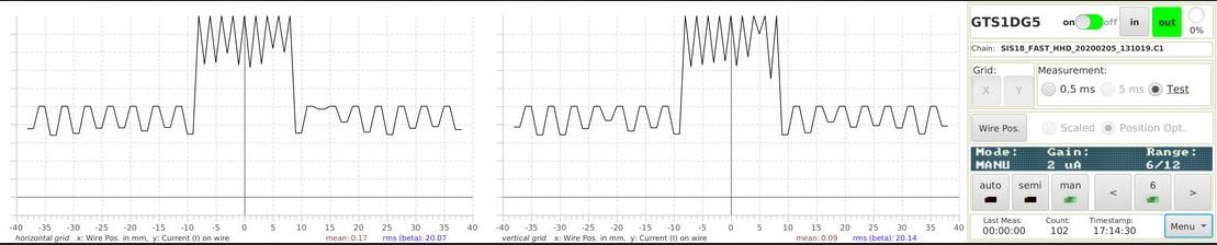
Testing can also be done from within the ProfileGrid app, but this requires a running pattern.
Just select Test, the test pattern in "Profile Grids" then looks like this (the channels
on the side are divided by two).
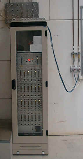
The detectors operate with 90% Ar + 10% CO2 gas at 1 bar. The gas flow can be controlled independently for the focal planes and is set to roughly 5 l/hour. Before the detectors are filled homogeneously gas flow has to be provided for some hours. The GSI detector laboratory (Dr. C.J. Schmidt, Mr. Michael Träger, Tel. 2639) takes care of the gas supply unit and has to be informed in advance. The gas flow is controlled, mixed and monitored from the cupboard in front of the cave entrance, see picture below.
However, as the detectors are usually not used in a gas amplification mode they can also run with no gas filling but just rough vacuum. For fast extracton this even is better as it avoids background and widened peaks. Instead of gas supply in this case a roughing pump can be connected via a hose.
 l
l