Doppler-shift Correction of Emitted ![]() -Rays
-Rays
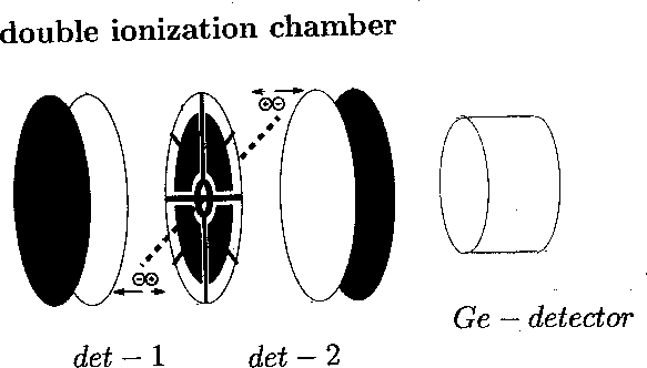
Figure 1: Experimental set-up with double ionization chamber
and Ge-detector positioned at ![]() .
.
A.) special geometry: Ge-detector at ![]()
Doppler-shift correction:
![]()
where ![]() is the measured Doppler-shifted
is the measured Doppler-shifted ![]() -ray energy
-ray energy
![]() for an excited fragment in det-1
for an excited fragment in det-1
![]() for an excited fragment in det-2
for an excited fragment in det-2
![]() is the polar emission angle of excited fragment
and
is the polar emission angle of excited fragment
and ![]() the fragment velocity
the fragment velocity
![]()
B.) general case: Ge-detector at ![]()
Doppler-shift correction:
![]()
where ![]() is the measured Doppler-shifted
is the measured Doppler-shifted ![]() -ray energy
-ray energy
![]()
![]()
for an excited fragment in det-1 and in det-2, respectively.
![]() is the polar emission angle of excited fragment
and
is the polar emission angle of excited fragment
and ![]() the fragment velocity
the fragment velocity
![]()
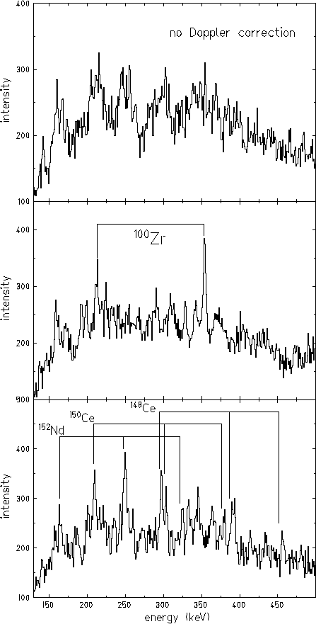
Figure 2: Fragment mass selected ![]() -ray spectra: no Doppler-shift
correction (top), Doppler-shift correction for the light fragment mass (center)
and Doppler-shift correction for the heavy fragment mass (bottom).
-ray spectra: no Doppler-shift
correction (top), Doppler-shift correction for the light fragment mass (center)
and Doppler-shift correction for the heavy fragment mass (bottom).