Experimental set-up
double ionization chamber
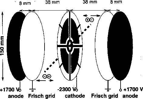
Figure 1: Inner setup of the double ionization chamber.
The thin ![]() source was mounted in the hole in the center of the cathode.
source was mounted in the hole in the center of the cathode.
momentum conservation:
![]()
![]()
![]()
![]() Cf-source:
Cf-source:
![]()
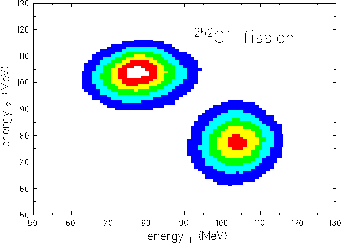
Figure 2: Energy of anode-1 versus energy of anode-2 measured with the
double ionization chamber.
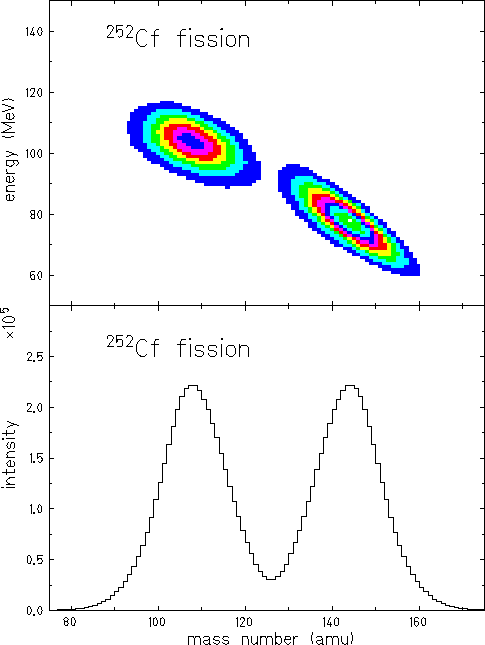
Figure 3: Energy versus mass number (top), fragment mass distribution (bottom).
Emission Angle of Fragments
drift-time of anode
![]() polar angle
polar angle ![]()
drift-time mesurement: start with central cathode signal,
stop with anode signal
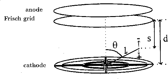
Figure 4: Determination of the polar angle ![]() from the measured
drift-time.
from the measured
drift-time.
![]()
![]()
![]()
![]()
polar angle of fragments:
![]()
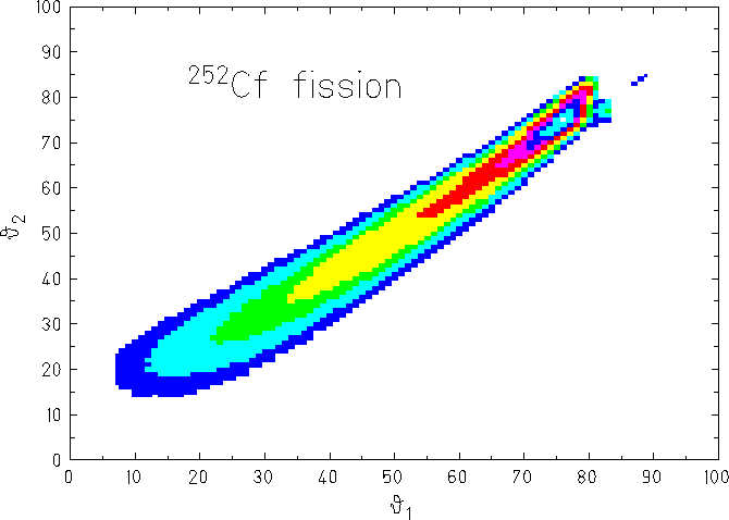
Figure 5: ![]() versus
versus ![]() distribution determined with the
double ionization chamber.
distribution determined with the
double ionization chamber.
Emission Angle of Fragments
energy signals of the four sectors depend on the orientaion of the fission axis
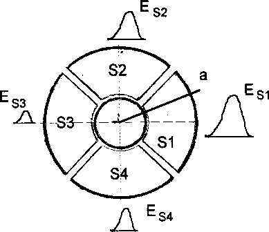
Figure 6: Determination of the azimuthal angle ![]() from the cathode signals.
from the cathode signals.
determination of energy ratios
![]()
![]()
azimuthal angle of fragments:
![]()
Energy Ratios for Different Emission Angles
![]()
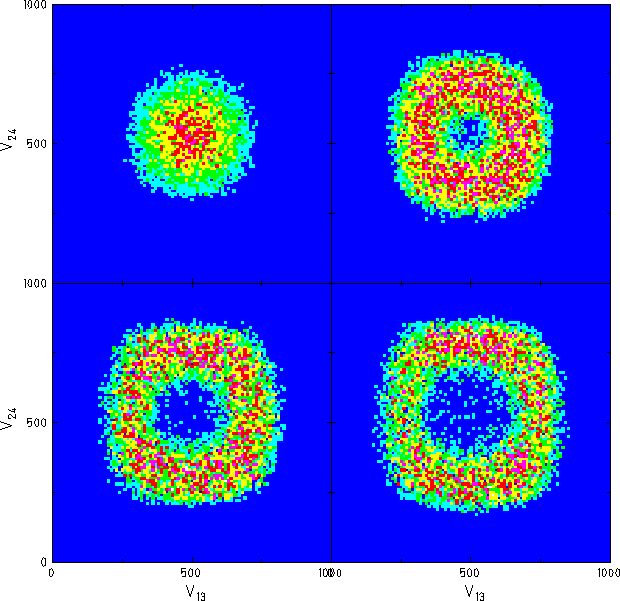
Figure 7: Energy ratios ![]() versus
versus ![]() determined from the cathode signals
for emission angles
determined from the cathode signals
for emission angles ![]() .
.