Segment Angles of the GSI-Clover Detector
A.) Transformation of a polar coordinate system from the target
position to a flat detector
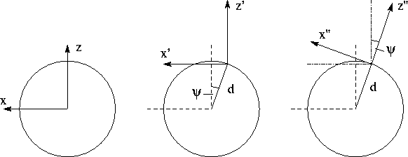
Figure: Left: polar coordinate system in target or source position
(y-axis points out of plane); center: coordinate system moved in detector
position (d=distance between detector and target, ![]() );
right: coordinate system rotated around the y-axis (
);
right: coordinate system rotated around the y-axis ( ![]() )
to measure events from the target.
)
to measure events from the target.
1.) Polar coordinate system with its origin in target position
(y-axis points upwards)

2.) The origin of the coordinate system is shifted to detector surface
(d = distance from detector surface to target position,
![]() -angle is negative for the displayed example in fig.1)
-angle is negative for the displayed example in fig.1)

3.) The coordinate system is rotated around y-axis
( ![]() -angle is negative for the displayed example in fig.1)
-angle is negative for the displayed example in fig.1)

Boundary condition: z'' = 0 for flat detector surface
![]()
One obtains the following relation for a point (x'',y'') on the detector
surface and the polar angle ![]() and azimuthal angle
and azimuthal angle ![]() :
:
B.) Calculation of the GSI-clover segment angles
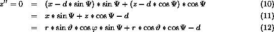
The GSI-clover detector has 16 position segments which are displayed in Fig.2.
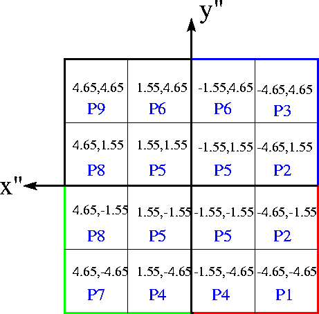
Figure: The centriods (x'',y'') of the 16 position segments of the
GSI-clover detector are given in cm. The central contacts are black and
blue (upper half from left to right) and green and red (lower half from
left to right).
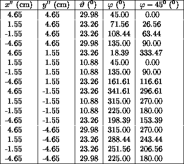
Table: Polar- ( ![]() ) and azimuthal (
) and azimuthal ( ![]() ) angles of
the GSI-clover segments for
) angles of
the GSI-clover segments for ![]() and d=11.4 cm
and d=11.4 cm
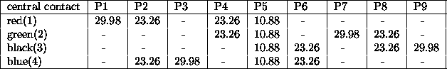
Table: Polar ( ![]() ) angles of the GSI-clover segments
for different central contacts (
) angles of the GSI-clover segments
for different central contacts ( ![]() , d=11.4 cm)
, d=11.4 cm)
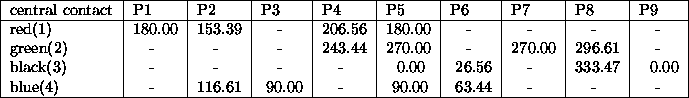
Table: Azimuthal ( ![]() ) angles of the GSI-clover segments
for different central contacts (
) angles of the GSI-clover segments
for different central contacts ( ![]() , d=11.4 cm)
, d=11.4 cm)
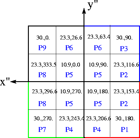
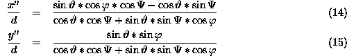
Figure: The centriods ![]() of the 16 position segments
of the GSI-clover detector in degree (
of the 16 position segments
of the GSI-clover detector in degree ( ![]() , d=11.4 cm).
The central contacts are black and
blue (upper half from left to right) and green and red (lower half from
left to right).
, d=11.4 cm).
The central contacts are black and
blue (upper half from left to right) and green and red (lower half from
left to right).
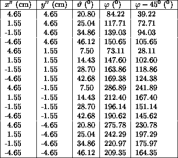
Table: Polar- ( ![]() ) and azimuthal (
) and azimuthal ( ![]() ) angles of
the GSI-clover segments for
) angles of
the GSI-clover segments for ![]() and d=11.4 cm
and d=11.4 cm
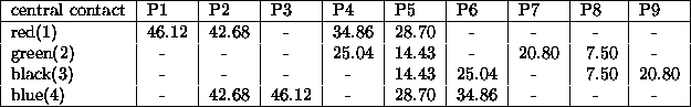
Table: Polar ( ![]() ) angles of the GSI-clover segments
for different central contacts (
) angles of the GSI-clover segments
for different central contacts ( ![]() , d=11.4 cm)
, d=11.4 cm)
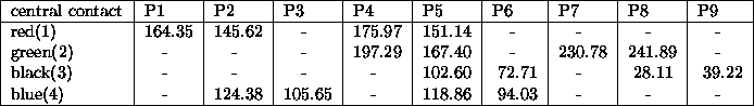
Table: Azimuthal ( ![]() ) angles of the GSI-clover segments
for different central contacts (
) angles of the GSI-clover segments
for different central contacts ( ![]() , d=11.4 cm)
, d=11.4 cm)
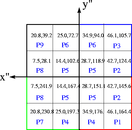
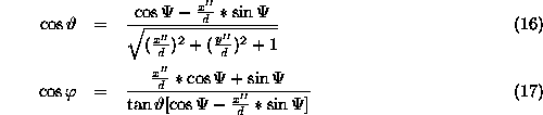
Figure: The centriods ![]() of the 16 position segments
of the GSI-clover detector in degree (
of the 16 position segments
of the GSI-clover detector in degree ( ![]() , d=11.4 cm).
The central contacts are black and
blue (upper half from left to right) and green and red (lower half from
left to right).
, d=11.4 cm).
The central contacts are black and
blue (upper half from left to right) and green and red (lower half from
left to right).