The ponycopter
Pony in the air using Raspberry Pi and brushless motor. Please refer to the GitHUB site for more information on this project.
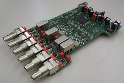
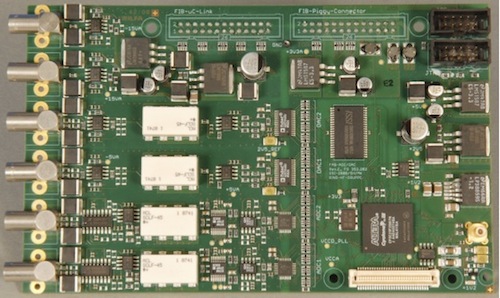
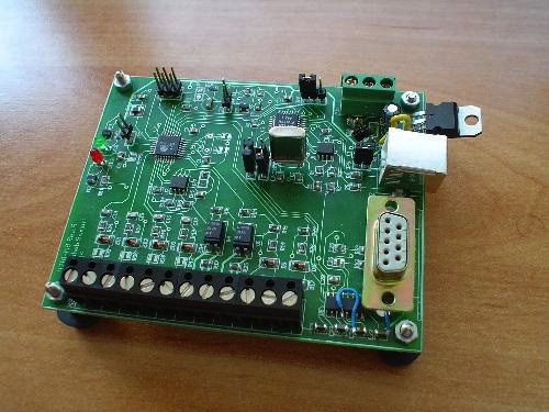
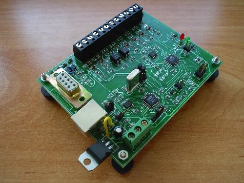
FPGA Mixed signal board
I made the revision A and B of this board as a part of the final project for the bachelor’s degree. Finally enhanced it up to revision D during my master’s degree. It is now a part of the controll system in the FAIR project.
EMG signal amplifier
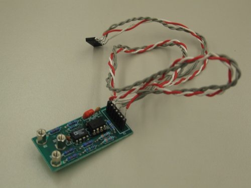
This is a prototype of an EMG signal amplifier with isolated channels.
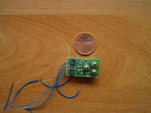
These are the electrodes. The first revision and the second one which is very small.
Single board computers
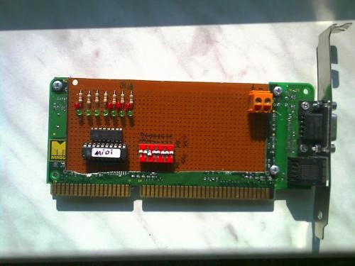
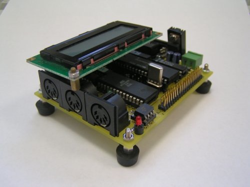
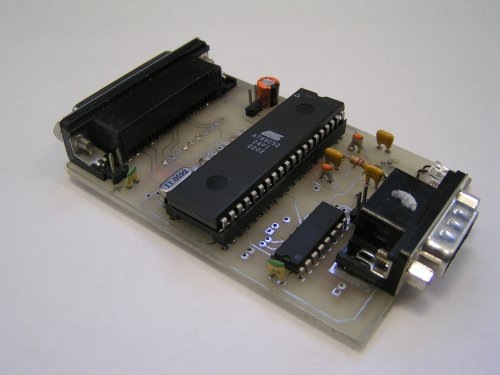
The MIDI controller board
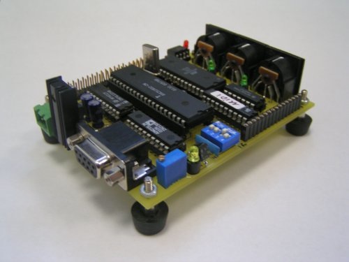
This is another SBC with MIDI interface. It costed me a lot of time and money. It is a full computer in a miniature scale. I actually connected the MIDI to a digital piano and could play tremolo on it, using midi messages that were generated on the MCU. The micro controller is a 8051 derivate an ATMEL AT89C51RD2 so the structure was not that flexible. For example only one UART and the problem of changing the baud rates to be able to switch between serial communications and MIDI. The good thing about the micro controller was it’s being in circuit programmable though. ATMEL provides some tools for this purpose, such as FLIP and ATMEL-ISP. I used the SDCC compiler bundle which runs well under under FreeBSD and *nix. I fabricated the board in Germany, with 150um track/space and 300um hole size technology. The quality of the board was really good. I didn’t order solder masks because it would become more expensive. Here are the pics:
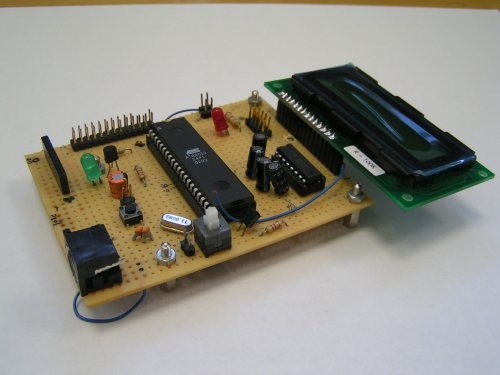
AVR microcontroller board
This was a SBC. A general purpose microcontroller board using the ATMEGA 8. I used this board for many of my test projects. U2IO-M8 stands for Universal USB Input Output Module and the 8 is there because of the processor. It was a really important turning point in my design career because: With this board I said
- Hello RISC processor, Goodbye CISC processor
- Hello SMD, Goodbye Through Hole
- Hello Free CAD Software, goodbye commercial CAD software
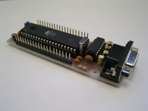
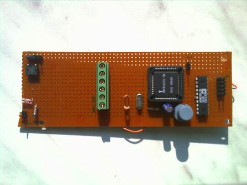
MOD RD2
This is my first SBC (single board computer) that really worked. A generall purpose controller board with ATMEL’s AT89C51RD2 controller which has ISP function. Almost all of useful pins are on the connectors.
 
8051 Microcontroller modules
Two other 8051 Microcontroller modules. One of my first tries, a serial to parallel converter that never worked correctly. Even the line driver nearly exploded! So young I was! Why on earth would I need a serial to parallel converter??!!
The Old Mate: I used this board a lot. It got really populated, then I decided to design a PCB. The Old Mate had even a PS2 port!
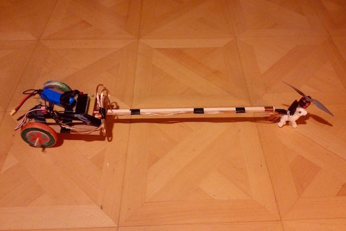
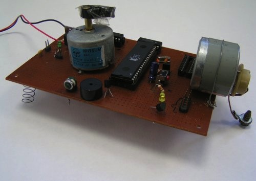
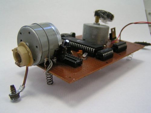
The jumping robot
Normally, robots have wheels, or legs which allows them to move around. This robot is unique in the way it moves around.It jumps up and down on the springs that are mounted at the bottom side of the board. The best place for the feat is the a flat surface of a table. The direction of the movement could be controlled using two DC motors. One is mounted on the top and the other at one side. There is an excentric load tied to each motor. The load for the side motor is heavier and is responsible for the jumping. The load for the top motor causes motion to left and right due to the angular momentum it generates. he system is naturally controllable by the computer, in this case a terminal program for sending. The computer cable is not visible in the photo. Note that the excentric load at the side won’t touch the ground. Here is a view:
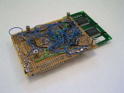
A CAN conrtoller board
Which never worked.
Audio circuits
Audio amplifiers and pre amplifiers
The one below is an audio amplifier using the LM386N from National Semiconductors. It is a fine, general purpose audio amplifier.
This is another pre amplifier that I calculated and built on a perf board. It consist of 2 BC547 transistors. It works fine. :-) I used it for electric guitar pre amplification for quite some time.
![]()
![]()
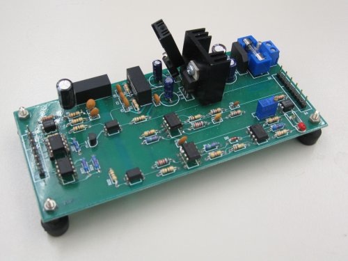
In the following amplifier I used an Instrumentation Amplifier from Analog, the popular AD620. It was not the most cost effective way to build an amplifier, in fact it is a little over engineered! But it works fine. The second stage is a TL072 from ST. The stages are coupled with capacitors. It was pretty tricky to get all the wires right. There is a perfect twin-T notch filter on 50Hz for the main interference. The rest is simple, an off board bipolar push-pull stage to without cross-over bridge gives the fuzzy sound to the guitar. And the best part, it works, loud and clear. But as you may guess, such a design could be very sensitive to EMI. And this one is indeed. So if I go off hook with the wireless telephone near the guitar, the amp becomes quiet.
This the worst amplifier I’ve ever built!!! But I learned a lot while designing it. A really good experience, since I calculated all the values by myself. I attached a CD-Player to the input and to my surprise (and my neighbor’s surprise: it was 11:00 pm!) I got something out of the speaker. The music was loud but totally distorted. Here is a view: Note the 250V capacitor near all those 0805s! I simply ran out of caps! ;-)
Misc circuits
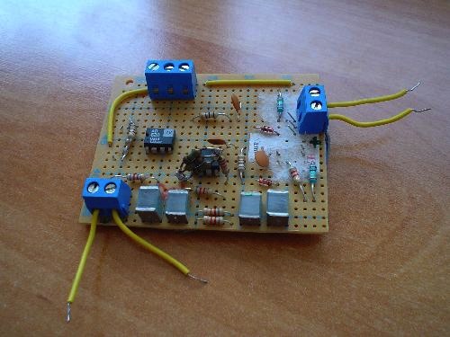
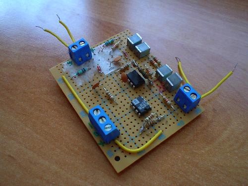
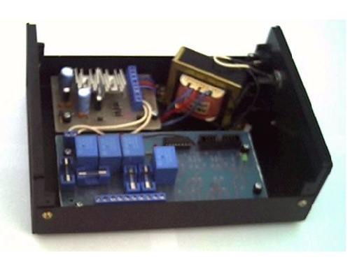
Relay interface
This is an interface for high current switching. I used one ULN2003 Darlington sink driver together with circuit protection diodes for the current throwback of the relays. The LEDs signal which channel is on. The circuit is connector to a power supply which I also made. All brought together in one nice box. The PCB quality was good. I was happy. :-)
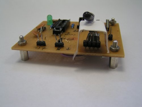
An infrared detector: This circuit detects an object which is located up to 10cm away from the electronic eye. Note that I have separated the receiver from the sender (top diode) because the sender diode doesn’t emit an straight beam. It worked well.
A nice try for understanding the concepts behind the op-amp circuits. And now I really know how it works, event hough I blew one computer power supply with this board on that day!
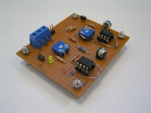
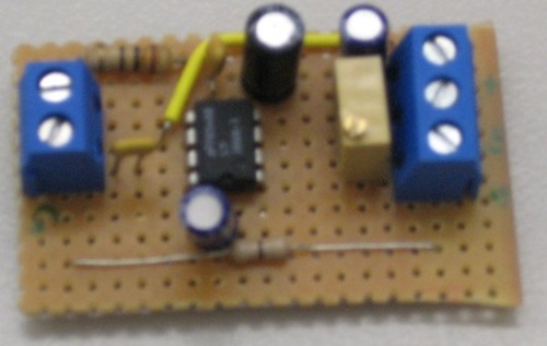
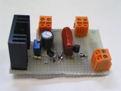
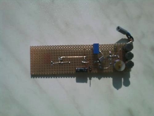
Home made +-12V Split Power Supply
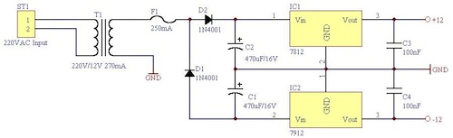
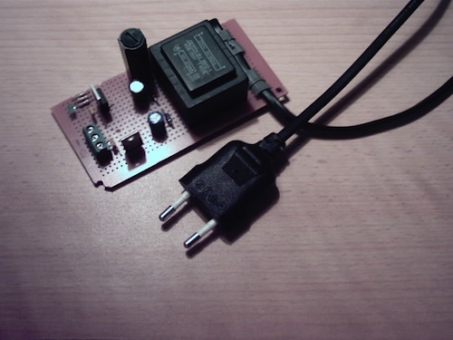
For a while, I used a PC’s power supply unit taken from an old box. But that was not a good idea, at least I didn’t like to have such a bulk on my desk. So I decided to make a small circuit on a perf board. Following is the schematic diagram of the circuit. The circuit consist of a half wave rectifier which is made of two 1N4001 diodes. The outputs are filled with two 470uF electrolyte capacitors in a way that it’s enough to see an almost flat signal on the scope. Both channels are now regulated using 7812 and 7912. The output noise is reduced when the signal passes through the bypass capacitors. I also soldered a green LED with 2.4 KOhm (in my case 1k +1k+330R) on the negative channel to see if the circuit is on. The reason for coupling if with the negative supply was simply because the negative regulator provides more juice than his fellow positive. There is a 250mA fuse ( the black tower in the photo!) which placed directly after the transformer. Here is a shot from the final state of the perf board.
Warning! This circuit is dangerous because it uses high voltages. Do not attempt to build it unless you are sure about what you are doing!
Another power supply
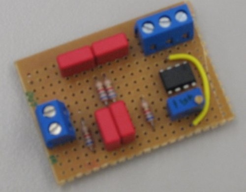
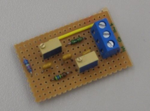
Twin T Notch filters
I had some problems with the 50Hz hum which was induced to my circuit. After searching for a good solution I made two notch filters which astonishingly had good results. These filters are Twin-T filters. The first one is fixed, the second one is a variable notch. The potentiometer allows adjusting over a small range.
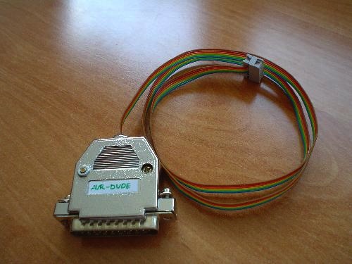
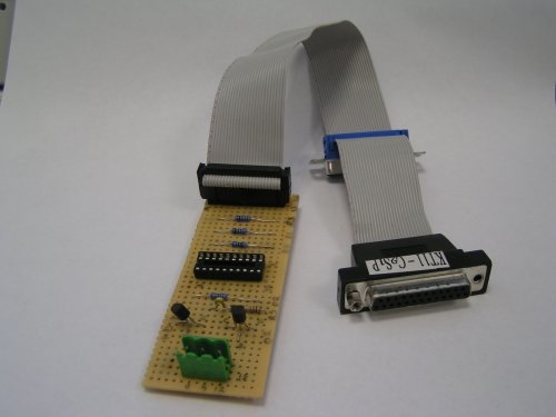
Microcontoller Programmers
These are two programmers. One for the AVR based on the [AVRDUDE](http://www.nongnu.org/avrdude/) project and the other for the 802051. The AVRDude worked well. But the other: Remember not to define a problem inside another problem! In this case I built another board with AT892051. For programming that one, I made this board. Now you must imagine if I had some bug, I couldn’t easily track it.
A radio
Which never worked.
An ISA card interface
Which never worked.