Travelling MUSIC is a newly designed MUSIC which is fabricated at the detector laboratory at GSI. Specifications and operation manuals of this detector are given below.
Specifications
Mechanical Operations
Voltage
Anode voltage
Anode filter-circuitry has been implemented. The high voltage required to bias the anodes, goes through the preamplifiers. It is strongly filtered within the preamplifier. The safe current limit on the anodes is 1 Amp.
Anode voltage: + (150 - 220) V. But it should not go beyond 1 kV which is acceptable for the preamplifiers. Beyond 1 kV, it can cause irreparable damage to the preamplifiers.
Appropriate cabling is foreseen (with respect to screening as well as HV-stability). If the connections are done correctly, the current displayed on the screen of the Mesytec module, should be practically zero (basically ~5 nA or below).
During the engineering run (December 2019) and beam time (February - May 2020), the anode voltage was connected with a BNC cable from Meshütte through the port S4 288 and the detector was situated in the S4 area of the FRS.
The anode HV-supply is crucial. Higher quality and clean supply is required (Mesytec MHV-4 is used).
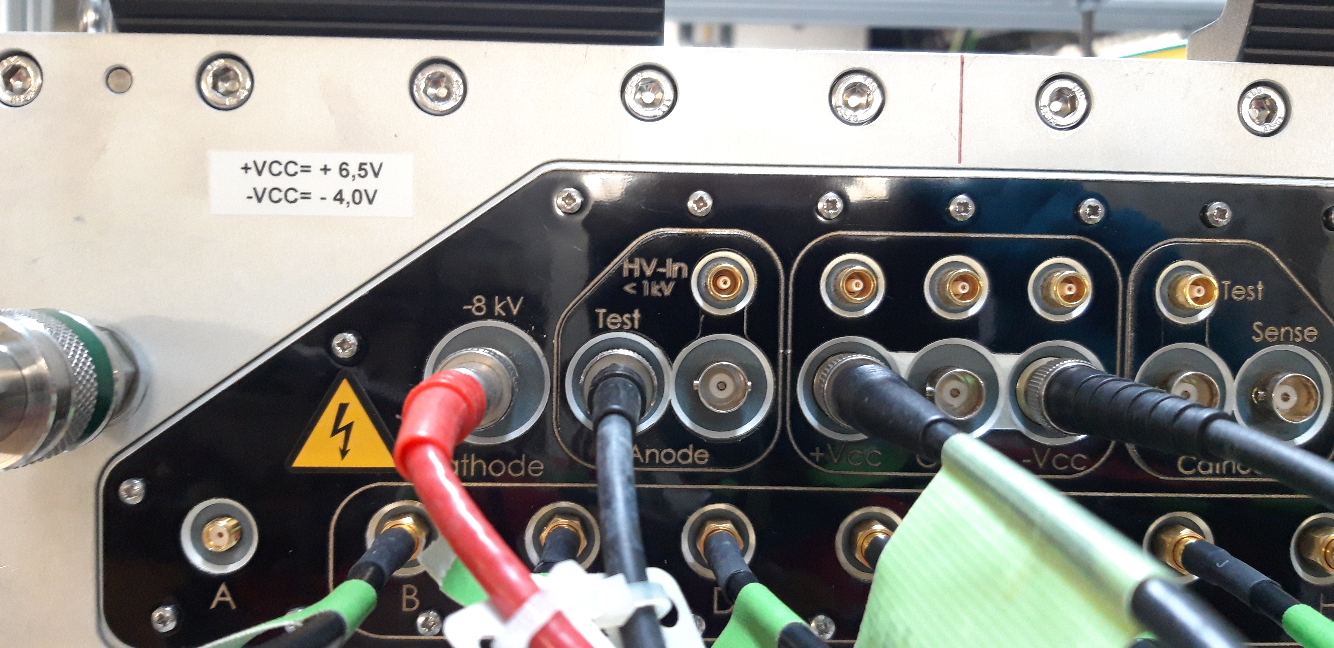
NOTE: Please connect the Anode voltage in the "Test" as the "Test" connector inside is swapped with "HV-In" connectors (both LEMO and BNC connectors). Information obtained from Julien Taieb during the engineering run (December 2019).
Cathode voltage
Cathode filter-circuitry has been implemented.
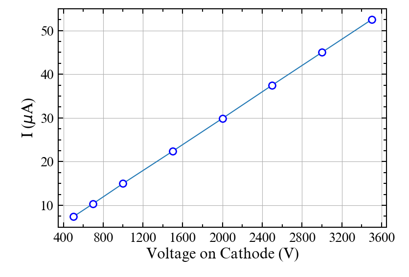
Cathode voltage: nominal voltage for P10 gas (90% Ar + 10%CH4), is -3500 V.
The corresponding current should be around 50 μA for this voltage. But DO NOT go beyond -8 kV.
Appropriate cabling is foreseen (with respect to screening as well as HV-stability).
During the test of the detector at the detector lab (October 2019) and engineering run at GSI (December 2019), we used an ISEG module (EHS40100n) which can be remotely controlled and manual of this module can be found here and here. Please note that for this ISEG module special type of SHV connection (SHV-10) is needed. Few of cables with these connections are supposed to be at Meshütte. The operation manual for this module can be found here.
During the 2020 beam time at GSI, we used CAEN high voltage system (CAEN SY4527) and the module we used is CAEN AG523N (6 ch Neg 12kV 1mA) at channel 0. The corresponding cable is labelled as "Tr Cathode Neg 8KV". The voltage control was done by GECO software (connection number 10.0000).
Parameters set in GECO software:
V0set = 3500 V (change here the desired voltage)
I0Set = 100 μA (set a safe current limit, 100 μA is a safe limit)
SV Max = 8000 V (DO NOT go beyond 8 kV)
Some redundant variables of the GECO software (not necessary):
V1set = 0 V
I1set = 100 μA
Rup = 50 Vps
RDwn = 50 Vps
Trip = 10 sec
Low voltage power supply for Preamplifiers
The low voltage on the negative rail should not exceed -4 V (-Vcc) and for positive rail, it should be +6.5 V (+Vcc) sharp. High stability low-voltage power supply needed to be used (KEYSIGHT E36313A). The operation manual of this module can be found here.
A good cable connection is needed to reduce the noise level. You may connect via LEMO or BNC type connectors (both are bridged internally) but good quality shielded cables to reduce the noise level (BNC cable) is preferable. The goal is to reach the value which is better than 5 mV (according to Julien, 2-3 mV can be reachable). Cables from the power supply source should be tied together in order to avoid some unnecessary capacitance built-in, thus affecting in noise level.
The switch implemented at the side panel of the detector displays green light if the low voltages are present ("ready" state). The voltages can be applied to the preamps by pushing this button AFTER their complete installation on every channel. Blue light shows the "ON" state.
The low voltage supply really depends on the voltage regulators that are on the motherboards. The current reading depends on the number of preamps connected. Typical values of current reading from the screen of the power supply are given below when all the preamplifiers are connected included the screening anodes:
| Mode | Current on +Vcc | Current on -Vcc |
|---|---|---|
| Ready | 10.093 mA | 0.012 mA |
| ON | 0.353 A | 0.196 A |
Preamplifiers
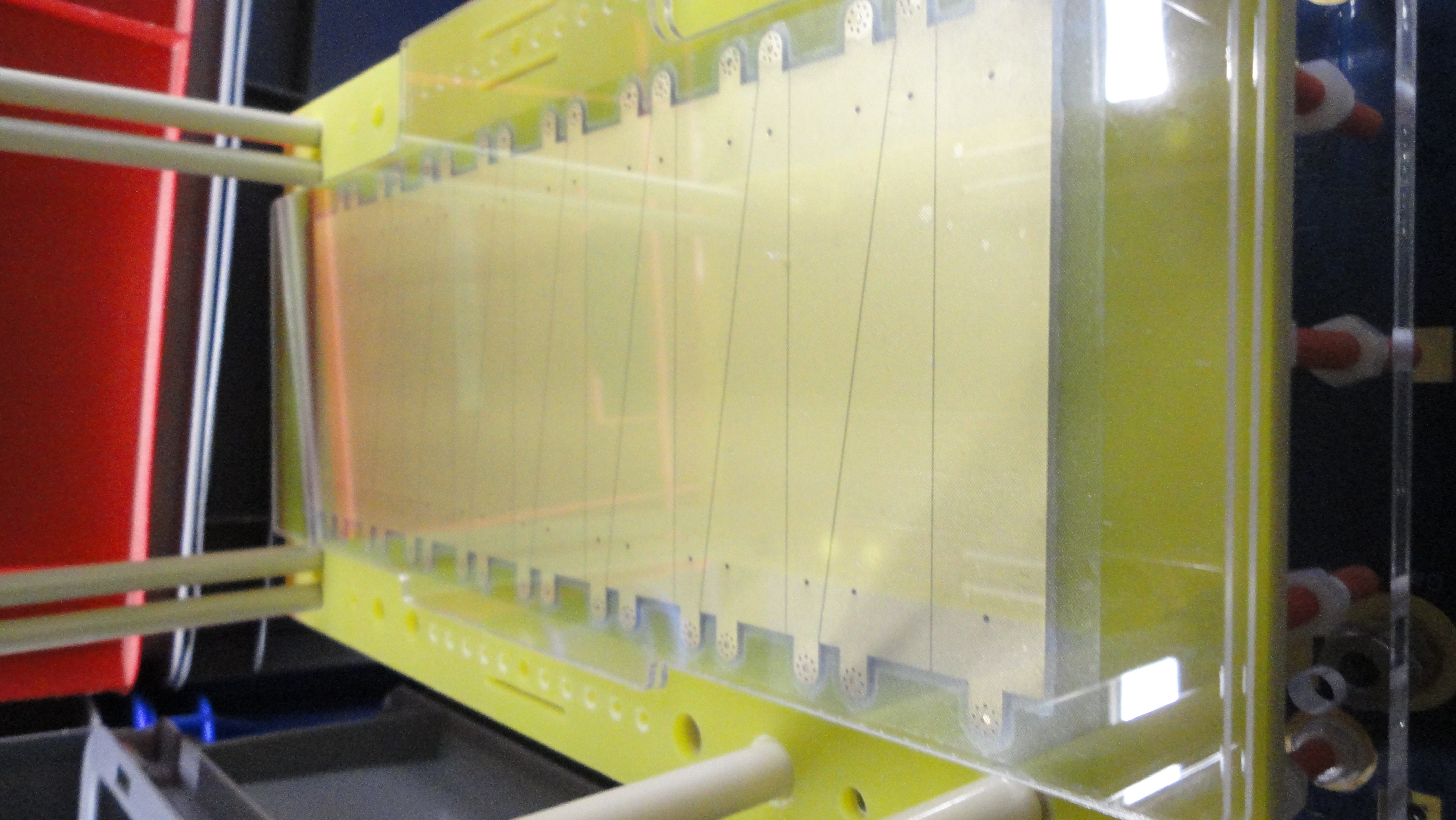
Low-noise charge sensitive preamplifiers are developed by CEA Bruyeres-le-Chatel (named MUSAMP). Connections to the preamplifiers are on the sidewall of the MUSIC.
For mounting, dismount/unscrew the aluminum screening-hood covering the PreAmps. This hood provides EM-tight mounting of the preamps.
Two different types of preamplifiers:
1. The standard preamps or low-gain preamplifier (MUSAMP v6) could operate from Uranium down to Lithium.
2. The high gain preamps (MUSAMP v5). These should be used exclusively to detect ions lighter than zinc (Z=30). Their charge resolution is better than that of the standard preamps for the lighter ions (zinc down to helium).
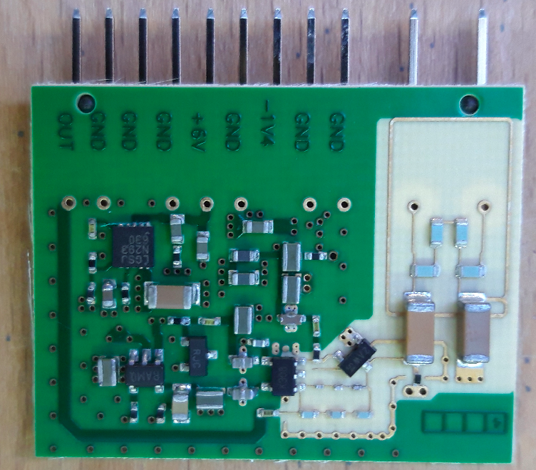

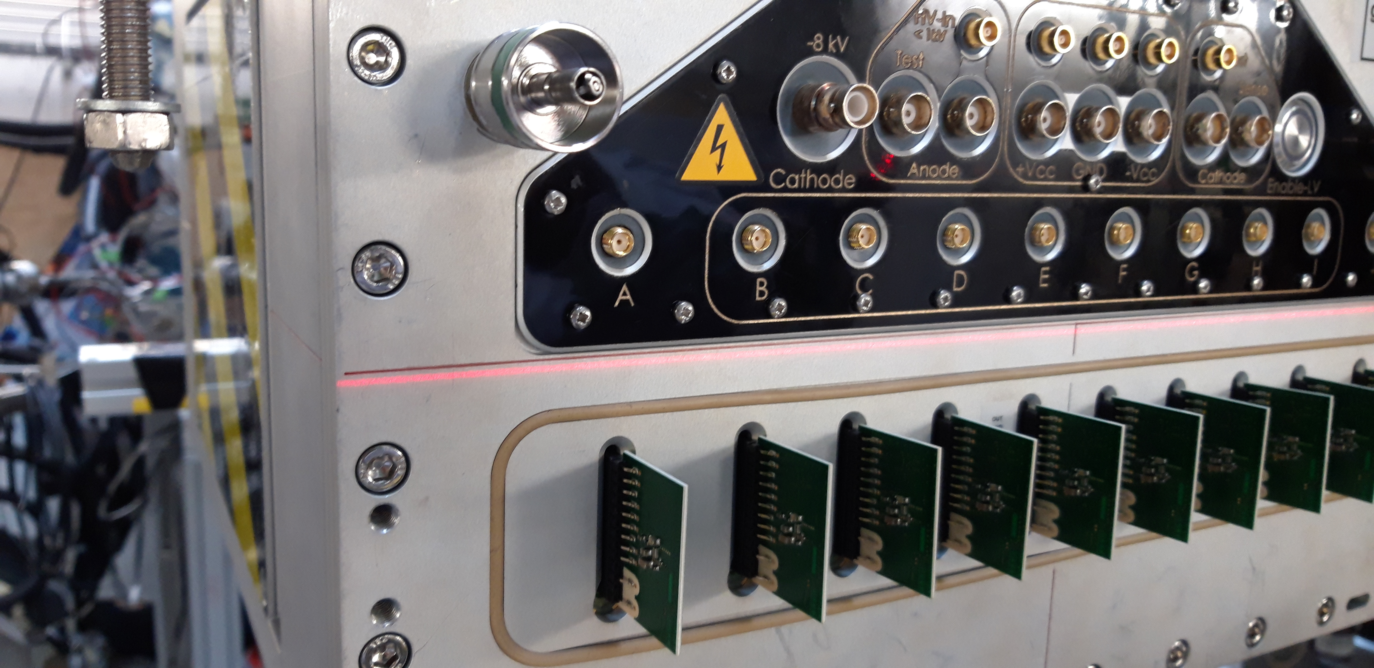
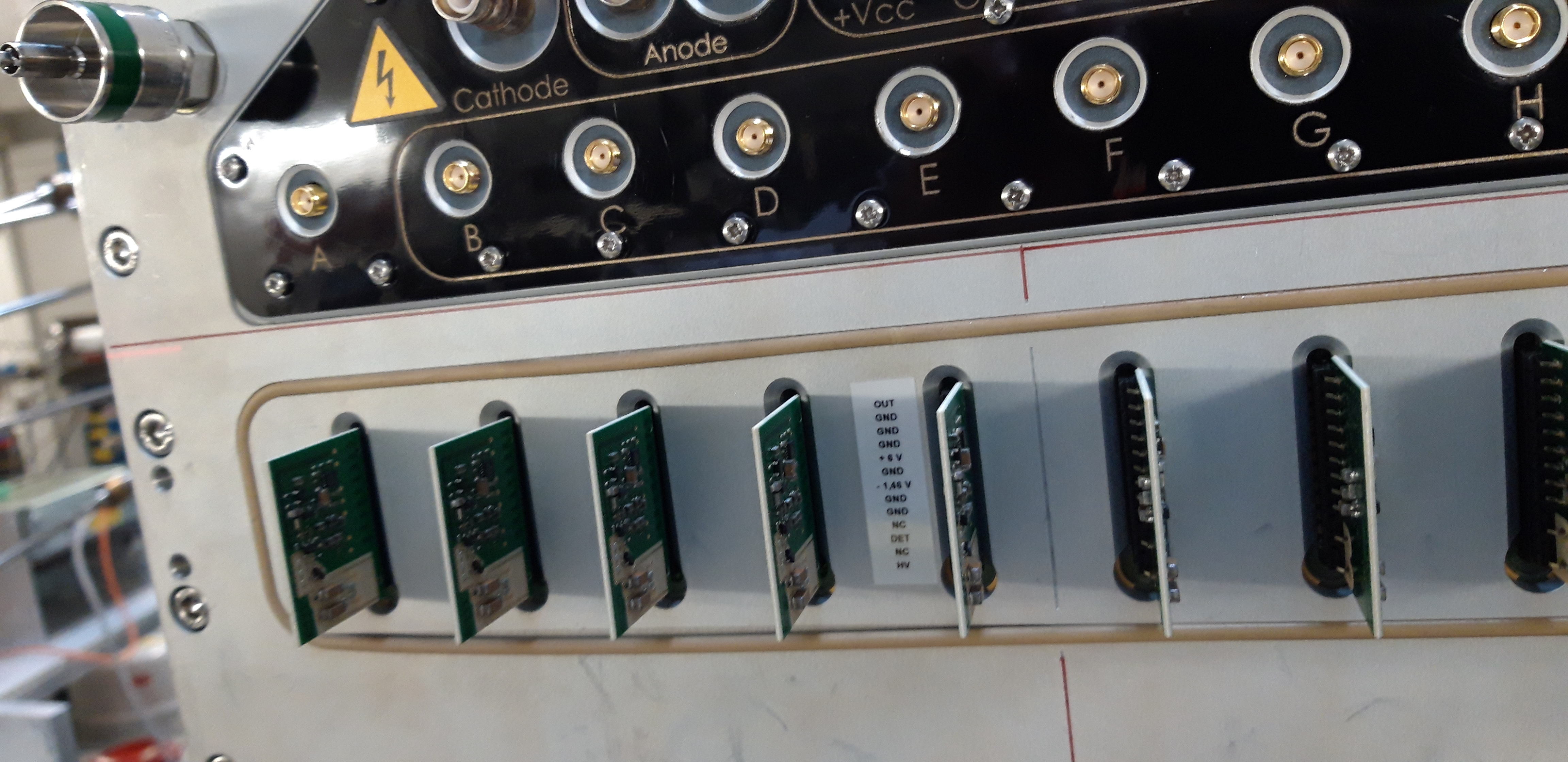
The preamplifiers are chips of 28 mm x 36 mm with a 11-pin connector. Among the 11 pins, 9 are labelled on one side of the preamplifier (See Fig. 6). GND stands for low impedance ground connection: 6 of them, -1V4 and +6V are the low voltage biasing (-4.0 V and +6.5 V are required for Travelling MUSIC) and "OUT" stands for the output of the preamplifier to be connected to the main amplifier. One is related to the anode high voltage and the remaining one is connected to the anode. Please also note the orientation of the preamplifiers while connecting to the MUSIC inside the protective box.
The preamplifiers provide one unipolar output. It is 50 Ohm terminated at the preamplifier level. The oscilloscope should also include a 50 Ohm termination. The preamplifiers are protected against damages originating from moderate sparks in the MUSIC chamber.
The white area of the PCB never be touched with bare hands. The high voltage parts and the input stage of the preamplifier are within the white area. Traces of grease in that area may result in an additional leakage current, which would negatively impact the nuclear charge
resolution. Input j-FET is also located in that area and bare hand contact could destroy the j-FET due to electrostatic discharges.
For any questions regarding the preamplifiers, please contact Julien Taieb from CEA Bruyeres-le-Chatel.
Gas regulation system
The gas supply has to be the one regulated for flow and pressure at the same time on a relatively high level of precision. A dedicated setup is provided by Serv' Instrumentation.
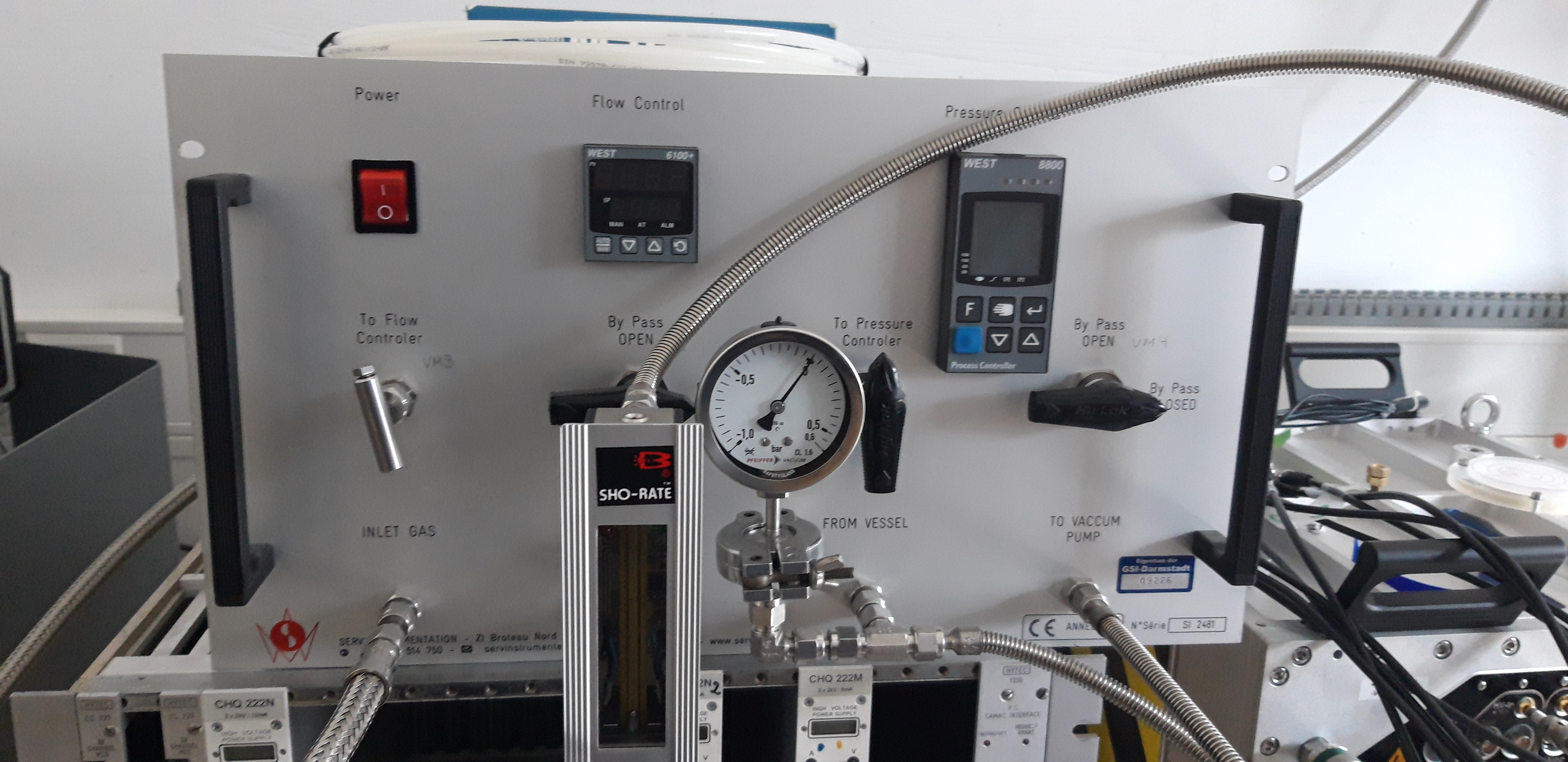
In Fig. 7, a setup for the gas supply system is shown. We put an additional manometer and flow meter to confirm the values shown by the flow controller (P6100+) and the pressure controller (N8800). The process diagram can be found here. The electrical diagram which is inside the gas supply system can be found here.
The connection lines should be made of corrugated stainless steel throughout the whole connection, thus, reinforcing clean gas inside the chamber. The suggestion is not to put a pipe longer than 10 m and not to put plastic pipes. Due to general problems with large volumes, it is neither feasible nor possible to have several inputs/volumes managed at the same outlet.
Please connect the outlet first to the MUSIC, which is labelled as a blue female connector. Please make sure there is no pressure built-up on the line prior to connection (self-closing valves are foreseen). The input line is coded in green and is equipped with a male connector. Both are of metrical 6mm SWAGELOK type.
Be aware of the correct operation of the regulating device, especially the internal pump used to keep the flow. Never operate the gas system in combination of the detector without the proper connections. Otherwise, there is a risk of destroying the chamber either by ex- or implosion!
Please do not open the valves on the chamber while removing the cables from the setup. Just unplug the gas-supply, exhaust line first, then inlet but without a big delay - preventing blowing up.
NOTE: For training how to operate the gas supply system, one can connect it to a dummy chamber roughly the same volume as the Travelling MUSIC. In addition, please check whether the vacuum pump is compatible with the type of the gas used.
Flow
Flush the chamber with operating gas (P10 or Ar/CO2 70/30 to 90/10) with 5-8 l/h before starting. Nominal flow should be one volume exchange per hour. Nominal pressure is close to the atmosphere. Be aware not to operate above 5 mbar overpressure (15 mbar may be already too much) and take a critical look at the bulging of the windows.
The gas-types used in this gas system also include aggressive gases containing CF4 as well as flammable ones ranging from P10 to even P90. Of course, one has to check with the local safety authorities). This gas system is calibrated with N2 gas. The conversion factor between different gases:
100% N2 (reference calibration Gas) 0-13 Nl/h N2 = 0-6Nl/h CF4 = 0-10 Nl/h 90%AR+10%CH4
To establish stable gas conditions, one should not wait for too long in advance with the flushing. 6h is the absolute minimum for such detectors of that size.
Flow through the detector volume should be such that the pressure drop stays in the limits acceptable for the windows not to blow up. It is mainly all about stable conditions between the inlet (blowing) and the outlet (sucking). And of course, the fragility of material and structures within the detector play a certain role. Thus, for more flow, the more/the faster extraction is needed and this is the main role of the controller anyway.
The windows of the Travelling MUSIC were designed and glued carefully with stronger foils than absolutely necessary to facilitate the handling. Thus, it is expected that the windows can withstand the overpressure (~ 5 mb). Concerning under-pressure, the windows were not designed explicitly for this operation mode. Usually, a bending outwards of 10-20 mm does not harm too much, but in the long run, it weakens the windows due to stretching of the foils. The lifetime then strongly depends on the number of up-down-up cycles.
Never open the self-closing gas valves to open-air - they are to prevent the impurities to enter the chamber, mainly oxygen and water. Especially water is extremely hard to get rid of at a nominal flow.
How to operate the gas system
Set the parameters of the customized gas-distribution device containing the PID controllers: N8800 (pressure) and P6100+ (flow). These PID controllers are manufactured at West Instruments.
Short manuals for both controllers for easy operation:
For N8800 controller operation manual can be found here.
For P6100+ controller operation manual can be found here.
While setting a pressure, usually, there is a swing-in operation and this oscillation is then damped to the set value. The nominal over-pressure should be between 5 and 10 mbar with respect to ambient pressure. Obviously, it may depend on how the whole system is set up, e.g. on the amount of dead/passive volumes with respect to the regulated ones, the size of the tubing/pressure losses, bypass lines, etc.
There are several parameters in the controller that one can set. Parameters of the controllers have been optimized so that set values for both controllers can be reached pretty fast.
The parameter values can be found here.
NOTE:
When the pressure/flow is stabilized, further adjustments are not needed. This system from Serv Instrumentation, does not have remote control access. Ethernet connection is not possible. However, for P6100+ there is a possibility to have an additional board to have RS485 ModBus RTU but for N8800 is not possible at all (at least the version we have; Type 8800-114-000F-069).
The gas supply system is working fine with the present settings as of April 2020. We used P10 gas. The flow controller is set to 6 l/h and the pressure controller is set to 1015 mbar. Please do not change the settings/parameters of the controllers other than the set value. If in doubt, one can train on this system by coupling to a dummy chamber.
Any other gas system will lead to larger drifts and consequently deterioration of the resolution. Anyway, if such this system has not been available due to some reason, then one can use the local infrastructure available. In this case just slowly increase the flow (and thus the pressure) until a reasonable bulging of the windows is maintained.
Electronics
An unipolar module from Mesytec MDPP-16 is used. There is a jumper in the module to change the dynamic range of the signal amplitude from 500 mV to 3 V. Pay attention to the pin connection of the jumper. ADC range is 8000 ch.
The gain of the amplifier can be changed by software. In data acquisition, look for RIO4 module where MDPP-16 is connected. Search for "main.cfg" file. Gain can be adjusted there.
In the same file shaping time (say 200 ns), differentiation time (say 200 ns) and search window according to trigger start (say [-1000 ns; 4000 ns]) can be adjusted.
Cabling
It is recommended to avoid any interconnection on the (signal) cabling and route all the cables all in parallel to the power (avoid loops). For signal cables, low capacity/low noise cables are needed. The RG174 is clearly not the best choice.
For best performance and to have good timing resolution, the highest quality coaxial cables are preferred to connect the SMA preamplifier output to the MDPP-16 module input. LMR195 cables (~ 5 m length) with SMA male connector on one end and LEMO male connector on the other end are preferred.
In addition, high-quality cables on every part, including the HV, are essential too.